


ED 15103-6 • MICROTECH III WSHP UNIT CONTROLLER 48 www.DaikinApplied.com
s
eleCTed
p
arameTers
I
nformaTIon
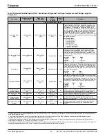
Table 21: Binary Input Status Bit Descriptions - Enfinity Single Stage Compressor (Models MHC/MHW, CCH/CCW, VFC/
VFW, LVC/LVW, VHC/VHF), Continued
Bit Number
Bit Description
Setting
Description
Unit Controller Jumpers
22 & 23
Fan Speed Selection
(2 Jumpers)
Jumper 5 = Open (0)
Single speed fan
Jumper 6 = Open (0)
Jumper 5 = Shorted (1)
Two speed fan
Jumper 6 = Open (0)
Jumper 5 = Open (0)
Three speed fan
Jumper 6 = Shorted (1)
24
Not used
Jumper 7 = Open (0)
25
Lead Compressor Options
(Unit controller software v3.1 and newer)
Jumper 8 = Open (0)
Compressor #1 is lead
Jumper 8 = Closed (1)
Compressor #2 is lead (dual compressor models only)
I/O Expansion Module Inputs
26
Compressor #2 Low Pressure Switch
Switch Closed (1)
Low Pressure Switch for compressor #2 is normal
Switch Open (0)
Low Pressure Switch for compressor #2 is in alarm
27
Compressor #2 High Pressure Switch
Switch Closed (1)
High Pressure Switch for compressor #2 is normal
Switch Open (0)
High Pressure Switch for compressor #2 is in alarm
28
Humidistat Dehumidification Request
Closed (1)
HGR Dehumidification is requested
Open (0)
HGR Dehumidification is not requested
29
Not used
N/A
30
Not used
N/A
31
Previous Unit Heat/Cool/Dehumid Mode
Provided by unit controller
Provides mode awareness in Fan Only state
(0=Heating, 1=Cooling or Dehumidification)
1. This switch is effective only when the network scheduling is not in use.
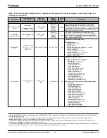
Table 22:
Bit Description for SmartSource Single and Two Stage Compressor (Models GSH/GSV, GTH/GTV and GCV)
Bit Number
Bit Description
Setting
Description
Unit Controller Jumpers
0
Normal/Test Mode
Jumper 1 = Open (0)
Normal operation
Jumper 1 = Shorted (1)
Service/Test mode operation
1
Fan Operation
Jumper 2 = Open (0)
Continuous fan operation
Jumper 2 = Shorted (1)
Cycling fan operation
2
Loop Fluid
Jumper 3 = Open (0)
Water loop fluid
Jumper 3 = Shorted (1)
Glycol loop fluid
3
Freeze Fault Protection
Jumper 4 = Open (0)
LWT Freeze Fault Protection is disabled
Jumper 4 = Shorted (1)
LWT Freeze Fault Protection is enabled
4
Room Sensor Setpoint Adjust Range
Jumper 5 = Open (0)
Short range: -5º to +5º F (-2.78º to +2.78º C)
Jumper 5 = Shorted (1)
Long range: 55º to 95º F (12.78º to 35º C)
5
Thermostat/Room Sensor
Jumper 6 = Open (0)
Thermostat control
Jumper 6 = Shorted (1)
Room sensor control
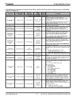
6
Compressor Heating Source
Jumper 7 = Open (0)
Allows compressor Heating mode operation
Jumper 7 = Shorted (1)
Disables compressor Heating mode operation
7
I/O Expansion Module
Jumper 8 = Open (0)
I/O Expansion Module is not present
Jumper 8 = Shorted (1)
I/O Expansion Module is required
Unit Controller Inputs
8
Compressor Low Pressure Switch
Switch Closed (1)
Compressor Low Pressure Switch is normal
Switch Open (0)
Compressor Low Pressure Switch is in alarm
9
Compressor High Pressure Switch
Switch Closed (1)
Compressor High Pressure Switch is normal
Switch Open (0)
Compressor High Pressure Switch is in alarm
10
Emergency Shutdown
Open (0)
Unit shuts down
11
Local Occupancy Switch
Switch Open (0)
Unoccupied
1
Switch Closed (1)
Occupied
12
Thermostat Heat Stage #3
(O – Terminal)
Switch Closed (1)
Third stage of thermostat heating is requested
13
Thermostat Fan Request
(G – Terminal)
Switch Closed (1)
Thermostat fan operation is requested


