


C
omprehensIve
d
aTa
T
ables
www.DaikinApplied.com 17
ED 15103-6 • MICROTECH III WSHP UNIT CONTROLLER
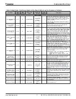
Table 9: Analog Values - SmartSource Single and Two Stage, Enfinity Large Two Compressor, Continued
Point Name
Object
Type/
Instance
Read/
Write
Access
2
BACnet Object
Name
Range/Default
(in Units)
Non-
volatile
Memory
1
Description
ANALOG VALUES
Hydronic Cooling ON
Setpoint
AV:27
W
cpHydroClgOnSpt
50 to 70ºF
10 to 21.12ºC
Default:
55ºF / 12.78ºC
Y
Specifies the Entering Water Temperature (EWT) Hydronic
Cooling setpoint for units with a waterside economizer.
Hydronic cooling is enabled if the EWT is below the value
of AV27. It is allowed to operate in conjunction with
compressor cooling.
If the EWT drops below the fixed value of 35ºF, hydronic
cooling is disabled.
Hydronic Setpoint
Differential
AV:28
W
cpHydronicDiff
2 to 10ºF
1.11 to 5.56ºC
Default:
5ºF / 2.78ºC
Y
Sets the hydronic heating and cooling hysteresis that
determines the Effective OFF setpoints.
Low Leaving Water
Temp Differential
AV:29
W
cpLowLwtDiff
2 to 15ºF
1.11 to 8.34ºC
Default:
7ºF / 3.89ºC
Y
The Low Leaving Water Temperature Differential setpoint is
used to calculate the Freeze Fault setpoint. AV29 is added
to the selected Compressor Low Suction Temp Protection
SP (AV11 or AV12) to then determine the Freeze Fault
temperature, which is based on LWT. After the Freeze
Fault condition has been activated, the Freeze Fault alarm
must be manually reset when the LWT is above the lockout
temp for the alarm to clear.
Low EWT Setpoint for
Glycol
AV:30
W
cpLowEwtSptGly
15 to 40ºF
-9.44 to 4.45ºC
Default:
28ºF / -2.22ºC
Y
Value of the Low Entering Water Temperature (EWT)
setpoint when using a glycol loop fluid. The compressor(s)
are disabled in the heating mode when the low EWT
condition exists. Unit controller configuration jumper JP3
must be shorted in order to select glycol as the loop fluid
type. The hysteresis differential is fixed at 2ºF.
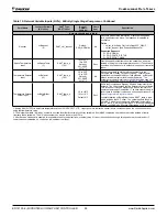
Low EWT Setpoint for
Water
AV:31
W
cpLowEwtSptWtr
40 to 65ºF
4.44 to 18.34ºC
Default:
55ºF / 12.78ºC
Y
Value of the Low Entering Water Temperature (EWT)
setpoint when using water loop fluid. The compressor(s)
are disabled in the heating mode when the low EWT
condition exists. Unit controller configuration jumper JP3
must be open in order to select water as the loop fluid type.
The hysteresis differential is fixed at 2ºF.
Hydronic Heating ON
Setpoint
AV:32
W
cpHydroHtgOnSpt
70 to 158ºF
21.11 to 70ºC
Default:*
90ºF / 32.22ºC
Y
Specifies the Entering Water Temperature Hydronic Heating
setpoint for units with a hydronic heating coil. Hydronic
heating is not allowed to operate in conjunction with
compressor heating.
*A default value of 70ºF / 21.12ºC applies to the following:
• SmartSource (Series2) v6.1 and older
•
Enfinity Large Two Compressor (SS2C) v1.1 and
older
Second Stage
Setpoint Differential
AV:33
W
cpStg2SptDiff
1 to 5ºF
0.55 to 2.78ºC
Default:
2ºF / 1.11ºC
Y
Determines the Second Stage Heating and Cooling ON
setpoints from the First Stage ON setpoints for units
controlled by room sensors.
Compressor Low
Pressure Alarm Delay
AV:34
W
cpLowPresAlmDly
0 to 120 sec
Default: 30 sec
Y
Specifies the time delay between the low pressure input
and alarm generation for compressor(s).
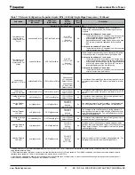
Temperature Setpoint
Offset Input
AV:35
C
SetptOffset
-18 to +18ºF
-10 to +10ºC
Default: 0º
N
Shifts the Occupied and Standby Effective Setpoints via
the network. The Unoccupied Effective Setpoints are not
affected. This is the Short Range Setpoint used when
a remote room sensor setpoint adjust is disabled.
7
The
network override will revert back to its default value upon
.
Third Stage Heating
Setpoint Differential
AV:36
W
cpStg3SptDiff
1 to 10ºF
0.55 to 5.56ºC
Default:
6ºF / 3.33ºC
Y
Determines the Third Stage Heating ON setpoints from the
Second Stage ON setpoints for units controlled by room
sensors.
Fourth Stage Heating
Setpoint Differential
AV:37
W
cpStg4SptDiff
1 to 10ºF
0.55 to 5.56ºC
Default:
6ºF / 3.33ºC
Y
Determines the Fourth Stage Heating ON setpoints from
the Third Stage ON setpoints for SmartSource (Series2)
units controlled by room sensors.
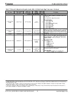
Fan Speed Output
AV:38
R
FanSpeedCmd
0 to 100%
N
Commanded fan speed percentage. AV38 is used in
conjunction with MSI-5 to indicate the Fan Runtime and
Fan Speed status.
Fan Runtime Totalizer
AV:39
W
FanRunHours
0 to 65535
Hours
Default: 0
Y
Total fan runtime hours.
8


