Operations Manual
OM 1191
Group:
Applied Air Systems
Part Number:
Date:
February 2013
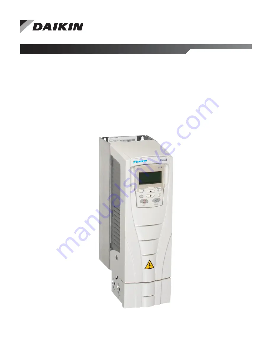
Daikin MD5
Variable Frequency Drive Controller
Page 1: ...Operations Manual OM 1191 Group Applied Air Systems Part Number OM 1191 Date February 2013 Daikin MD5 Variable Frequency Drive Controller ...
Page 2: ...munication Setup EFB 48 Serial Communication Selection 48 Serial Communication Configuration 48 Activate Drive Control Functions EFB 50 Controlling the Drive 50 Start Stop Direction Control 50 Input Reference Select 50 Miscellaneous Drive Control 51 Relay Output Control 52 Analog Output Control 53 PID Control Setpoint Source 53 Communication Fault 53 Feedback from the Drive EFB 54 Pre Defined Feed...
Page 3: ... Red LED 78 History 78 Correcting alarms 78 Alarm Listing 78 Maintenance 80 Maintenance Intervals 80 Heatsink 80 Drive Module Fan Replacement 80 Frame Sizes R1 R4 80 Frame Sizes R5 and R6 81 Frame Sizes R7 and R8 81 Capacitors 81 Control Panel 81 Cleaning 81 Battery 81 Technical Data 82 Ratings 82 Ratings 208 240 volt drives 82 Ratings 380 480 volt drives 82 Ratings 500 600 volt drives 83 Symbols ...
Page 4: ...off from the input terminals of the MD5 there may be dangerous voltage from external sources on the terminals of the relay outputs DANGER When the control terminals of two or more drives are connected in parallel the auxiliary voltage for these control connections must be taken from a single source which can either be one of the drives or an external supply DANGER Disconnect the internal EMC filte...
Page 5: ...odes are Standard Display Mode Shows drive status information and operates the drive Parameters Mode Edits parameter values individually Start up Assistant Mode Guides the start up and configuration Changed Parameters Mode Shows changed parameters Fault Logger Mode Shows the drive fault history Drive Parameter Backup Mode Stores or uploads the parameters Clock Set Mode Sets the time and date for t...
Page 6: ... functions currently assigned to the two soft keys Lower middle displays the current time if configured to show the time Operating the Drive Auto Hand The very first time the drive is powered up it is in the auto control AUTO mode and is controlled from the Control terminal block X1 To switch to hand control HAND and control the drive using the control panel press and hold the or button Pressing t...
Page 7: ...s not saved are cancelled Each individual parameter setting is valid immediately after pressing SAVE 7 Select EXIT to return to the listing of parameter groups and again to return to the main menu For detailed hardware description see the Appendix on page 88 NOTE The current parameter value appears below the highlighted parameter To view the default parameter value press the UP DOWN buttons simult...
Page 8: ...modifications not saved are cancelled 7 Select EXIT to return to the listing of parameter groups and again to return to the main menu To complete the control connections by manually entering the parameters see Parameters on page 12 For detailed hardware description see the Technical Data on page 82 NOTE The current parameter value appears below the highlighted parameter To view the default paramet...
Page 9: ...owing considerations apply for all macros When using a direct speed reference in AUTO mode connect the speed reference to analog input 1 AI1 and provide the START command using digital input 1 DI1 In HAND OFF mode the control panel provides the speed reference and START command When using process PID connect the feedback signal to analog input 2 AI2 As a default the control panel sets the Setpoint...
Page 10: ...the UP DOWN buttons and select SAVE Restoring defaults To restore the factory default settings select the application macro HVAC Default Control wiring Each macro has specific requirements for control wiring For general details about the MD5 control wiring terminals see Control Terminal Descriptions on page 85 Specific wiring requirements are included with each macro description OM 1191 MD5 VFD 10...
Page 11: ...er 9902 to 1 The diagram below shows typical wiring using this macro When using direct speed reference in AUTO mode or process PID see General Considerations on page 9 Figure 5 MD5 HVAC Defaults Table 3 Parameters Changed Relative to HVAC Default Parameter Value Parameter Value None Default macro Application Macros www DaikinApplied com 11 OM 1191 MD5 VFD ...
Page 12: ...tional device for fast copying of parameters to unpowered drives FlashDrop allows easy customization of the parameter list e g selected parameters can be hidden For more information see MFDT 01 FlashDrop User s Manual 3AFE68591074 English 1 USER S1 SAVE 3 USER S2 SAVE With these it is possible to save two different user parameter sets into the drive permanent memory for later use Each set contains...
Page 13: ...easured by the MD5 0109 OUTPUT VOLTAGE 0 2 0 VdN 1 V The voltage applied to the motor 0110 DRIVE TEMP 0 0 150 0 C 0 1 C The temperature of the drive power transistors in degrees Celsius 0111 EXTERNAL REF 1 0 0 500 0 Hz 0 30000 rpm 0 1 Hz 1 rpm External reference REF1 in rpm or Hz units determined by parameter 9904 0112 EXTERNAL REF 2 0 0 100 0 0 0 600 0 for torque 0 1 External reference REF2 in 01...
Page 14: ... the three relay outputs Available if OREL 01 Relay Output Extension Module is installed See parameter 0122 0124 AO 1 0 0 20 0 mA 0 1 mA The analog output 1 value in milliamperes 0125 AO 2 0 0 20 0 mA 0 1 mA The analog output 2 value in milliamperes 0126 PID 1 OUTPUT 1000 0 1000 0 0 1 The PID controller 1 output value in 0127 PID 2 OUTPUT 100 0 100 0 0 1 The PID controller 2 output value in 0128 P...
Page 15: ...ters in Group 34 Panel Display on page 34 0138 PROCESS VAR 2 1 Process variable 2 Defined by parameters in Group 34 Panel Display on page 34 0139 PROCESS VAR 3 1 Process variable 3 Defined by parameters in Group 34 Panel Display on page 34 0140 RUN TIME 0 00 499 99 kh 0 01 kh The drive s accumulated running time in thousands of hours kh Cannot be reset 0141 MWH COUNTER 0 65535 MWh 1 MWh The drive ...
Page 16: ...ote on page 1 163 The counter value is accumulated till it reaches 65535 after which the counter rolls over and starts again from 0 Can be reset with parameter 4509 ENERGY RESET resets all energy calculators at the same time 0176 SAVED AMOUNT 1 0 0 999 9 0 1 Energy saved in local currency remainder when the total saved energy is divided by 1000 See the note on page 1 163 To find out the total save...
Page 17: ...STPMODE_R Reserved 8 STPMODE_EM Reserved 9 STPMODE_C Reserved 10 RAMP_2 Reserved 11 RAMP_OUT_0 REF_CONST 12 RAMP_HOLD REF_AVE 13 RAMP_IN_0 LINK_ON 14 RREQ_LOCALLOC REQ_STARTINH 15 TORQLIM2 OFF_INTERLOCK 0302 FB CMD WORD 2 1 Read only copy of the Fieldbus Command Word 2 See parameter 0301 0303 FB STS WORD 1 1 Read only copy of the Status Word 1 The drive sends status information to the fieldbus con...
Page 18: ...em error 14 EXT FAULT 2 MOTOR PHASE System error 15 EARTH FAULT OUTP WIRING Param setting fault 0306 FAULT WORD 2 1 Read only copy of the Fault Word 2 See parameter 0305 0307 FAULT WORD 3 1 Read only copy of the Fault Word 3 See parameter 0305 0308 ALARM WORD 1 1 When an alarm is active the corresponding bit for the active alarm is set in the Alarm Words Each alarm has a dedicated bit allocated wi...
Page 19: ...if real time clock is not used or was not set Format on the Basic Control Panel The time since power on in 2 second ticks minus the whole days reported in 0402 30 ticks 60 seconds E g Value 514 equals 17 minutes and 8 seconds 514 30 0404 SPEED AT FLT 32768 32767 1 rpm 0 The motor speed rpm at the time the last fault occurred 0405 FREQ AT FLT 3276 8 3276 7 0 1 Hz 0 The frequency Hz at the time the ...
Page 20: ... digital input DI3 must be activated prior to the pulse in DI1 Start Reverse command is through a normally open push button connected to digital input DI2 In order to start the drive the digital input DI3 must be activated during the pulse in DI2 Connect multiple Start push buttons in parallel Stop is through a normally closed push button connected to digital input DI3 Connect multiple Stop push b...
Page 21: ...ove 7 EXT2 Selects external control location 2 EXT2 See parameter 1002 EXT2 COMMANDS for EXT2 s Start Stop Dir definitions See parameter 1106 REF2 SELECT for EXT2 s reference definitions 8 COMM Assigns control of the drive via external control location EXT1 or EXT2 based on the fieldbus control word Bit 5 of the Command Word 1 parameter 0301 defines the active external control location EXT1 or EXT...
Page 22: ...a fieldbus and analog input 1 AI1 combination as the reference source See Analog input reference correction below 10 COMMAI1 Defines a fieldbus and analog input 1 AI1 combination as the reference source See Analog input reference correction below 11 DI3U 4D RNC Same as DI3U 4D R above except that Changing the control source EXT1 to EXT2 EXT2 to EXT1 LOC to REM does not copy the reference 12 DI3U 4...
Page 23: ... 30000 rpm 0 1 Hz 1 rpm 60 0 Hz US 1800 rpm US Sets the maximum for external reference 1 The maximum analog input signal as a percent of full the signal in volts or amperes corresponds to REF1 MAX in Hz rpm Parameter 1302 MAXIMUM AI1 or 1305 MAXIMUM AI2 sets the maximum analog input signal Does not apply to Daikin MicroTech III applications 1106 REF2 SELECT 0 17 19 21 1 19 PID1OUT Selects the sign...
Page 24: ...e of three Constant Speeds 1 3 using DI4 and DI5 See above DI1 2 for code 11 DI5 6 Selects one of three Constant Speeds 1 3 using DI5 and DI6 See above DI1 2 for code 12 DI1 2 3 Selects one of seven Constant Speeds 1 7 using DI1 DI2 and DI3 Uses three digital inputs as defined below 0 DI de activated 1 DI activated DI1 DI2 DI3 Function 0 0 0 No constant speed 1 0 0 Constant speed 1 1202 0 1 0 Cons...
Page 25: ...Timed function can be used to change between the external reference and constant speeds when parameter 1201 CONST SPEED SEL 15 18 TIMED FUNC 1 4 or 19 TIMED FUN1 2 1 EXT CS1 2 3 If parameter 1201 15 18 TIMED FUNC 1 4 selects an external speed when this timed function 1 4 is not active and selects Constant speed 1 when it is active TIMED FUNCTION 1 4 Function 0 External reference 1 Constant speed 1...
Page 26: ...fault trip if the cause of the fault no longer exists 0 KEYPAD Defines the control panel as the only fault reset source Fault reset is always possible with control panel 1 DI1 Defines digital input DI1 as a fault reset source Activating the digital input resets the drive 2 6 DI2 DI6 Defines digital input DI2 DI6 as a fault reset source See DI1 above 7 START STOP Defines the Stop command as a fault...
Page 27: ...able 1 signal See fieldbus user s manual for detailed instructions 1 DI1 INV Defines an inverted digital input DI1 as the start enable 1 signal 2 6 DI2 INV DI6 INV Defines an inverted digital input DI2 DI6 as the start enable 1 signal See DI1 INV above 1611 PARAMETER VIEW 0 1 1 0 DEFAULT Selects the parameter view i e which parameters are shown Note This parameter is visible only when it is activa...
Page 28: ...mits 2015 MIN TORQUE 1 and 2016 MIN TORQUE 2 0 MIN TORQUE 1 Selects 2015 MIN TORQUE 1 as the minimum limit used 1 DI1 Defines digital input DI1 as the control for selecting the minimum limit used Activating the digital input selects MIN TORQUE 2 value De activating the digital input selects MIN TORQUE 1 value 2 6 DI2 DI6 Defines digital input DI2 DI6 as the control for selecting the minimum limit ...
Page 29: ...de The drive automatically selects the correct output frequency to start a rotating motor useful if the motor is already rotating and if the drive will start smoothly at the current frequency Cannot be used in multimotor systems 4 TORQ BOOST Selects the automatic torque boost mode SCALAR FREQ mode only May be necessary in drives with high starting torque Torque boost is only applied at start endin...
Page 30: ...n Range Resolution Default S 2202 ACCELER TIME 1 0 0 1800 0 s 0 1 s 30 0 s Sets the acceleration time for zero to maximum frequency for ramp pair 1 See A in the figure Actual acceleration time also depends on 2204 RAMP SHAPE 1 See 2008 MAXIMUM FREQ page 28 2203 DECELER TIME 1 0 0 1800 0 s 0 1 s 30 0 s Sets the deceleration time for maximum frequency to zero for ramp pair 1 Actual deceleration time...
Page 31: ...efault S 2605 U f RATIO 1 2 1 2 SQUARED Selects the form for the U f voltage to frequency ratio below field weakening point 1 LINEAR Preferred for constant torque applications 2 SQUARED Preferred for centrifugal pump and fan applications SQUARED is more silent for most operating frequencies Parameters www DaikinApplied com 31 OM 1191 MD5 VFD ...
Page 32: ... 1 DI1 Defines digital input DI1 as the external fault input Activating the digital input indicates a fault The drive displays a fault 14 EXT FAULT 1 and the drive coasts to stop 2 6 DI2 DI6 Defines digital input DI2 DI6 as the external fault input See DI1 above 1 DI1 INV Defines an inverted digital input DI1 as the external fault input De activating the digital input indicates a fault The drive d...
Page 33: ...quires a successful reset performed from the control panel or from a source selected by 1604 FAULT RESET SEL Example Three faults have occurred in the trial time The last is reset only if the value for 3101 NUMBER OF TRIALS is 3 or more 3102 TRIAL TIME 1 0 600 0 s 0 1 s 30 0 s Sets the time period used for counting and limiting the number of resets See 3101 NUMBER OF TRIALS 3103 DELAY TIME 0 0 120...
Page 34: ...igits desired to the right of the decimal point See the table for an example using pi 3 14159 8 BAR METER Specifies a bar meter display 9 DIRECT Decimal point location and units of measure are identical to the source signal See Group 01 Operating Data on page 13 parameter listing in section Complete parameter list on page 1 67 for resolution which indicates the decimal point location and the units...
Page 35: ...d on the control panel See parameter 3401 3415 SIGNAL3 PARAM 100 178 1 120 AI 1 Selects the third parameter by number displayed on the control panel See parameter 3401 3418 OUTPUT3 DSP FORM 0 9 1 5 0 0 Defines the decimal point location for the third display parameter See parameter 3404 3420 OUTPUT3 MIN Depends on selection 0 0 mA 3421 OUTPUT3 MAX Depends on selection 20 0 mA Sets the maximum valu...
Page 36: ...are disabled 1 DI1 Defines digital input DI1 as the timed function enable signal The digital input must be activated to enable the timed function 2 6 DI2 DI6 Defines digital input DI2 DI6 as the timed function enable signal 7 ACTIVE Timed functions are enabled 1 DI1 INV Defines an inverted digital input DI1 as the timed function enable signal This digital input must be de activated to enable the t...
Page 37: ... 59 58 2 s 12 00 00 AM Defines timer 3 daily stop time See parameter 3603 3612 START DAY 3 1 7 1 1 MONDAY Defines timer 3 weekly start day See parameter 3604 3613 STOP DAY 3 1 7 1 1 MONDAY Defines timer 3 weekly stop day See parameter 3605 3614 START TIME 4 00 00 00 23 59 58 2 s 12 00 00 AM Defines timer 4 daily start time See parameter 3602 3615 STOP TIME 4 00 00 00 23 59 58 2 s 12 00 00 AM Defin...
Page 38: ...normal operation this counter is increasing constantly 5307 EFB CRC ERRORS 0 65535 1 0 Contains a count of the messages with a CRC error received by the drive For high counts check Ambient electro magnetic noise levels high noise levels generate errors CRC calculations for possible errors 5308 EFB UART ERRORS 0 65535 1 0 Contains a count of the messages with a character error received by the drive...
Page 39: ...lter time seconds 6403 LOGGERS RESET 6 7 1 0 NOT SEL Defines the source for the reset of peak value logger and amplitude logger 2 0 NOT SEL No reset selected 1 DI1 Reset loggers on the rising edge of digital input DI1 2 6 DI2 DI6 Reset loggers on the rising edge of digital input DI2 DI6 7 RESET Reset loggers Parameter is set to NOT SEL 1 DI1 INV Reset loggers on the falling edge of digital input D...
Page 40: ...gger 1 current in percent of nominal current I2n 30 40 distribution 6418 AL1RANGE40TO50 0 0 100 0 0 1 Amplitude logger 1 current in percent of nominal current I2n 40 50 distribution 6419 AL1RANGE50TO60 0 0 100 0 0 1 Amplitude logger 1 current in percent of nominal current I2n 50 60 distribution 6420 AL1RANGE60TO70 0 0 100 0 0 1 Amplitude logger 1 current in percent of nominal current I2n 60 70 dis...
Page 41: ...r each PFA relay These assignments are defined in the following table and depend on the number of PFA relays number of parameters 1401 1403 and 1410 1412 with value 31 PFA the Autochange function status disabled if 8118 AUTOCHNG INTERV 0 0 and otherwise enabled No PFA relays Autochange disabled P 8118 Autochange enabled P 8118 0 DI1 Speed Reg Motor Not allowed DI2 DI6 Free 1 DI1 Speed Reg Motor DI...
Page 42: ...rd PFA Relay DI6 Free DI6 Fourth PFA Relay DI1 Free 5 Not allowed DI1 Free DI2 First PFA Relay DI3 Second PFA Relay DI4 Third PFA Relay DI5 Fourth PFA Relay DI6 Fifth PFA Relay 6 Not allowed Not allowed 3 DI3 Enables the Interlocks function and assigns a digital input starting with DI3 to the interlock signal for each PFA relay These assignments are defined in the following table and depend on the...
Page 43: ...lowed Not allowed 5 DI5 Enables the Interlock function and assigns a digital input starting with DI5 to the interlock signal for each PFA relay These assignments are defined in the following table and depend on the number of PFA relays number of parameters 1401 1403 and 1410 1412 with value 31 PFA the Autochange function status disabled if 8118 AUTOCHNG INTERV 0 0 and otherwise enabled No PFA rela...
Page 44: ...cations terminal See also Group 53 EFB PROTOCOL 2 N2 Enables fieldbus communication with the drive using Metasys N2 protocol via the RS485 serial link X1 communications terminal 3 FLN Enables fieldbus communication with the drive using FLN protocol via the RS485 serial link X1 communications terminal 4 EXT FBA The drive communicates via a fieldbus adapter module in option slot 2 of the drive 5 BAC...
Page 45: ...tual value 2 Actual value 3 Actual value 4 Actual value 5 Actual value 6 Actual value 7 Actual value 8 The content of these words is defined by profiles For details on the profiles used The MicroTech III control and the MD5 communicate over Modbus All Modbus values are factory set and tested N2 Binary output objects Analog output objects Binary input objects Analog input objects N2 protocol techni...
Page 46: ...earthed to a common ground Connect the RS485 link in a daisy chained bus without dropout lines To reduce noise on the network terminate the RS485 network using 120 Ω resistors at both ends of the network Use the DIP switch to connect or disconnect the termination resistors See following wiring diagram The MD5 termination resistor J 2 are active terminators This active circuit includes bins Pull up...
Page 47: ...Figure 8 Alternate Wiring Diagram Embedded Fieldbus www DaikinApplied com 47 OM 1191 MD5 VFD ...
Page 48: ...ve on the network with a unique value for this parameter Note For a new address to take affect the drive power must be cycled OR 5302 must first be set to 0 before selecting a new address Leaving 5302 0 places the RS485 channel in reset disabling communication 5303 EFB BAUD RATE Defines the communication speed of the RS485 link in kbits per second kbits s 1 2 kbits s 2 4 kbits s 4 8 kbits s 9 6 kb...
Page 49: ... has exceeded the interval set by parameter 3019 OFFLINE EFB Protocol is receiving messages NOT addressed to this drive ONLINE EFB Protocol is receiving messages addressed to this drive RESET EFB Protocol is in reset LISTEN ONLY EFB Protocol is in listen only mode 5310 EFB PAR10 Not used for Comm setup Sets the response turnaround time in milliseconds in addition to any fixed delay imposed by the ...
Page 50: ...r Modbus the protocol reference can depend on the profile used hence two columns in these tables One column refers to the Daikin Drives profile selected when parameter 5305 0 Daikin DRV LIM or 5305 2 Daikin DRV FULL The other column refers to the DCU profile selected when parameter 5305 1 DCU PROFILE See Daikin control profiles technical data section 2 The reference provides direction control a ne...
Page 51: ...O6 94 BV14 1606 LOCAL LOCK 8 COMM Source for local lock selection is the fieldbus Does not apply 40031 bit 14 1607 PARAM SAVE 1 SAVE Saves altered parameters to memory then value returns to 0 41607 40032 bit 2 BO18 N A1 1608 START ENABLE 1 7 COMM Not Recommended Source for start enable 1 is the fieldbus Command word Does not apply 40032 bit 2 BV20 1609 START ENABLE 2 7 COMM Not Recommended Source ...
Page 52: ...ocol Reference Modbus N2 FLN BACnet Daikin DRV DCU PROFILE 1401 RELAY OUTPUT 1 35 COMM Relay Output 1 controlled by fieldbus 40134 bit 0 or 00033 BO7 40 BO0 1402 RELAY OUTPUT 2 35 COMM Relay Output 2 controlled by fieldbus 40134 bit 1 or 00034 BO8 41 BO1 1403 RELAY OUTPUT 3 35 COMM Relay Output 3 controlled by fieldbus 40134 bit 2 or 00035 BO9 42 BO2 14101 RELAY OUTPUT 4 35 COMM Relay Output 4 con...
Page 53: ... to select the fieldbus as the setpoint source for PID loops Table 31 PID Control Setpoint Parameters Drive Parameter Value Setting Protocol Reference Modbus N2 FLN BACnet Daikin DRV DCU PROFILE 4010 SET POINT SEL Set 1 8 COMM VALUE 1 9 COMM AI1 10 COMM AI1 Setpoint is either Input Reference 2 AI1 Control requires parameter 1106 value comm Process PID setpoint Control requires parameter 1106 value...
Page 54: ...1 bit 2 BI2 21 BV Mailbox Read Write The MD5 provides a Mailbox function to access parameters that have not been pre defined by the protocol Using mailbox any drive parameter can be identified and read Mailbox can also be used to adjust parameter settings by writing a value to any parameter identified The following table describes the use of this function Table 34 Mailbox Read Write Parameters Nam...
Page 55: ...s 100 Feedback Integer Parameter Resolution Value of 100 Ref 100 Scaled Value 10 0 1 1500 rpm1 10 0 1 1500 RPM 100 15 rpm 100 0 1 500 Hz2 100 0 1 500 Hz 100 50 Hz 1 Assuming for the sake of this example that the Actual Value uses parameter 9908 MOT NOM SPEED as the 100 reference and that 9908 1500 rpm 2 Assuming for the sake of this example that the Actual Value uses parameter 9907 MOT NOM FREQ as...
Page 56: ...g normal network operation 5306 5309 parameter values act as follows at each drive 5306 EFB OK MESSAGES advances advances for each application message properly received and addressed to this drive 5307 EFB CRC ERRORS does not advance at all advances when an invalid message CRC is received 5308 EFB UART ERRORS does not advance at all advances when character format errors are detected such as parity...
Page 57: ...n for the drive is too short for the given installation The master is not polling the drive within the specified time out delay To correct increase the time set by parameter 3019 COMM FAULT TIME Fault 31 EFB1 For BACnet If the drive s control panel shows fault code 31 EFB1 the drive has an invalid Device Object Instance ID To correct use parameters 5311 and 5317 and establish a unique drive ID tha...
Page 58: ...op or high voltage problems before replacing any component assemblies Perform the following steps to determine if the EIA 485 transceiver is damaged a Power unit down b Remove bus wires and retighten connections c Turn bus termination ON d Measure impedance between B A MD5 164 ohms 5 If measurements are not within the specified range the EIA 485 transceiver is bad replace the assembly containing t...
Page 59: ...R NOTE For Present Value Access Types R Read only W Writeable C Commandable Commandable values support priority arrays relinquish defaults Binary Output Object Instance Summary The following table summarizes the Binary Output Objects supported Table 38 Binary Output Objects Instance ID Object Name Description Active Inactive Text Present Value Access Type BO0 RO1 COMMAND This object controls the o...
Page 60: ...t selects ext1 or ext2 as the active control source Control requires parameter 1102 value COMM EXT2 EXT1 C BV14 FAULT RESET This object resets a faulted drive The command is rising edge triggered Control requires parameter 1604 value COMM RESET NO C BV15 MBOX READ This object reads a parameter defined by AV25 MBOX PARAM and returns it in AV26 MBOX DATA READ RESET W BV16 MBOX WRITE This object writ...
Page 61: ...s the drive s accumulated energy usage in kW hours The value cannot be reset kWh R AV10 PRC PID FBCK This object is the Process PID feedback signal The corresponding drive parameter is 0130 Percent R AV11 PRC PID DEV This object is the Process PID output signal s deviation from its setpoint The corresponding drive parameter is 0132 Percent R AV12 EXT PID FBCK This object is the External PID feedba...
Page 62: ...drive parameters 5311 and 5317 object instance values must be unique and in the range 1 to 4 194 303 To use the drive s MS TP MAC ID as the device object instance value set drive parameter 5311 and 5317 0 BACnet requires a unique Device Object ID for each device on the BACnet network 5 Define a unique MS TP MAC ID Set drive parameter 5302 EFB STATION ID appropriate value Once this parameter is set...
Page 63: ...ique for each network IP and MSTP Network Number of 0 is reserved for broadcasts Device Object IDs must be unique across the entire BACnet network all IP and MSTP subnetworks Device Object IDs are 22 bits configurable via parameters 5311 and 5317 in MD5 The example Network Numbers and DeviceOIDs show a good way to maintain unique DeviceOIDs across the network Figure 9 Device Address Rules Embedded...
Page 64: ...t Instance ID using drive parameters 5311 and 5317 Default Both 5311 and 5317 0 which causes the MAC ID to double as the Device Object Instance For Device Object Instance values not linked to the MAC ID set ID values using 5311 and 5317 For IDs in the range 1 to 65 535 Parameter 5311 sets the ID directly 5317 must be 0 For example the following values set the ID to 49 134 5311 49134 and 5317 0 For...
Page 65: ...ically creatable using the CreateObject service 2 Whether objects of this type are dynamically detectable using the DeleteObject service 3 List of the optional properties supported 4 List of all properties that are writable where not otherwise required by this standard 5 List of proprietary properties and for each its property identifier datatype and meaning 6 List of any property range restrictio...
Page 66: ...or Name Vendor Identifier Model Name Firmware Revision Appl Software Revision Protocol Version Protocol Revision Services Supported Object Types Supported Object List Max APDU Length Segmentation Support APDU Timeout Number APDU Retries Max Master Max Info Frames Device Address Binding Database Revision Present Value Status Flags Event State Out of Service Units Priority Array Relinquish Default P...
Page 67: ...for DeviceNet All of the FBA protocols can also be configured for the Daikin Drives profile Configuration details depend on the protocol and profile used These details are provided in a user s manual supplied with the FBA module Details for the Daikin Drives profile which apply for all protocols are provided in Daikin drives profile technical data on page 89 Control interface In general the basic ...
Page 68: ...n drives profile technical data section Reference The contents of each REFERENCE word Can be used as speed or frequency reference Is a 16 bit word comprised of a sign bit and a 15 bit integer Negative references indicating reversed rotation direction are indicated by the two s complement of the corresponding positive reference value The use of a second reference REF2 is supported only when a proto...
Page 69: ...uired for each control function The last column in each table below is deliberately blank See the user s manual supplied with the FBA module for the appropriate entry Start Stop Direction Control Using the fieldbus for start stop direction control of the drive requires Drive parameter values set as defined below Fieldbus controller supplied command s in the appropriate location The location is def...
Page 70: ...RELAY OUTPUT 4 Relay Output 4 controlled by fieldbus 14111 RELAY OUTPUT 5 Relay Output 5 controlled by fieldbus 14121 RELAY OUTPUT 6 Relay Output 6 controlled by fieldbus 0122 RO 1 3 STATUS Relay 1 3 status 0123 RO 4 6 STATUS Relay 4 6 status 1 More than 3 relays requires the addition of a relay extension module NOTE Note Relay status feedback occurs without configuration as defined below Analog O...
Page 71: ...sponse 3019 COMM FAULT TIME Set time delay before acting on a communication loss Feedback from the Drive FBA Inputs to the controller drive outputs have pre defined meanings established by the protocol This feedback does not require drive configuration The following table lists a sample of feedback data For a complete listing see all parameters listed in Complete parameter descriptions Scaling To ...
Page 72: ...OMP SWTYPE 630Fh 5 Reserved FF6Bh 101 SERF CORRUPT FF55h 6 DC UNDERVOLT 3220h 102 Reserved FF55h 7 AI1 LOSS 8110h 103 SERF MACRO FF55h 8 AI2 LOSS 8110h 104 Reserved FF55h 9 MOT TEMP 4310h 105 Reserved FF55h 10 PANEL LOSS 5300h 201 DSP T1 OVERLOAD 6100h 11 ID RUN FAIL FF84h 202 DSP T2 OVERLOAD 6100h 12 MOTOR STALL 7121h 203 DSP T3 OVERLOAD 6100h 14 EXTERNAL FLT 1 9000h 204 DSP STACK ERROR 6100h 15 ...
Page 73: ...limited by 2001 2002 speed Frequency 100 par 9907 0 0 100 par 9907 Final reference limited by 1104 1105 Actual motor speed limited by 2007 2008 frequency Actual Values As described earlier in Control interface Actual Values are words containing drive values Actual Value Scaling For Actual Values scale the feedback integer using the parameter s resolution See Complete parameter descriptions section...
Page 74: ...ve signals that it has detected a severe error or fault by Enabling the red LED on the drive LED is either steady on or blinking Setting an appropriate bit in a Fault Word parameter 0305 to 0307 Overriding the control panel display with the display of a fault code Stopping the motor if it was on The fault code on the control panel display is temporary Pressing any of the following buttons removes ...
Page 75: ...motor Supply disturbances 5 RESERVED Not used 6 DC UNDERVOLT Intermediate circuit DC voltage is not sufficient Check for and correct Missing phase in the input power supply Blown fuse Undervoltage on mains 9 MOT TEMP Motor is too hot based on either the drive s estimate or on temperature feedback Check for overloaded motor Adjust the parameters used for the estimate 3005 3009 10 PANEL LOSS Panel c...
Page 76: ...or speed is greater than 120 of the larger in magnitude of 2001 MINIMUM SPEED or 2002 MAXIMUM SPEED These are factory set and tested Contact your local Daikin sales representative if there is a problem Check for and correct Adequacy of motor braking torque Applicability of torque control Brake chopper and resistor 25 RESERVED Not used as of the publication of this manual 26 DRIVE ID Internal fault...
Page 77: ... NOM VOLT 1 73 Pn 3 0 Where Pn 1000 9909 MOTOR NOM POWER if units are kW or Pn 746 9909 MOTOR NOM POWER if units are HP e g in US 1006 EXT ROMISSING Parameter values are inconsistent Check for the following Extension relay module not connected and 1410 1412 RELAY OUTPUTS 4 6 have non zero values 1007 PAR FBUSMISSING Parameter values are inconsistent Check for and correct A parameter is set for fie...
Page 78: ... always required Use Alarm listing below to find and address the root cause of the problem Alarm Listing The following table lists the alarms by code number and describes each Table 56 Alarms by Code Numbers Alarm Code Display Description 2001 OVERCURRENT Current limiting controller is active Check for and correct Excessive motor load Insufficient acceleration time parameters 2202 ACCELER TIME 1 F...
Page 79: ...VERRIDE This alarm warns that the Override function is active which may start the motor 2021 START ENABLE 1 MISSING This alarm warns that the Start Enable 1 signal is missing To control Start Enable 1 function use parameter 1608 To correct check Digital input configuration Communication settings 2022 START ENABLE 2 MISSING This alarm warns that the Start Enable 2 signal is missing To control Start...
Page 80: ...fins accumulate dust from the cooling air Since a dusty heatsink is less efficient at cooling the drive overtemperature faults become more likely In a normal environment not dusty not clean check the heatsink annually in a dusty environment check more often Clean the heatsink as follows when necessary 1 Remove power from drive 2 Remove the cooling fan see Figure 12 and Figure 13 3 Blow clean compr...
Page 81: ... lowering the ambient temperature It is not possible to predict a capacitor failure Capacitor failure is usually followed by a input power fuse failure or a fault trip Contact Daikin if capacitor failure is suspected Replacements for frame size R5 and R6 are available from Daikin Do not use other than Daikin specified spare parts Control Panel Cleaning Use a soft damp cloth to clean the control pa...
Page 82: ... 2 0 R1 11 8 3 0 R1 16 7 5 0 R1 24 2 7 5 R2 30 8 10 0 R2 46 2 15 0 R3 59 4 20 0 R3 74 8 25 0 R4 88 0 30 0 R4 114 40 0 R4 143 50 0 R6 178 60 0 R6 221 75 0 R6 248 100 R6 Ratings 380 480 volt drives Abbreviated column headers are described in Symbols on page 83 Table 59 Ratings 380 480 volt drives Valid up to 40 C 104 F Frame Size I2n A Pn HP Three phase supply voltage 380 480 V 3 3 1 5 R1 4 1 2 R1 6...
Page 83: ...where full motor power is required oversize the drive so that the derated value provides sufficient capacity For example if your application requires 15 4 A of motor current and a 12 kHz switching frequency calculate the appropriate drive size requirement as follows The minimum size required 15 4 A 0 80 19 25 A Where 0 80 is the derating for 12 kHz switching frequency see Switching frequency derat...
Page 84: ...ables or to either X1 28 or X1 32 for RS485 cables Route control cables to minimize radiation to the cable Route as far away as possible from the input power and motor cables recommend at least 20 cm 8 in where practical Where control cables must cross power cables make sure they are at an angle as near 90 as possible Stay at least 20 cm 8 in from the sides of the drive where practical Use care in...
Page 85: ...e but single shielded twisted multi pair cable is also usable Control Panel Cable If the control panel is connected to the drive with a cable use only Category 5 Patch ethernet cable Drive s Control Connection Terminals The following table provides specifications for the drive s control terminals Frame Size Control Maximum Wire Size Torque mm2 AWG Nm lb ft All 1 5 16 0 4 0 3 Control Terminal Descr...
Page 86: ...must be 10 V or 10 V between that input and DCOM The 24 V may be provided by the MD5 X1 10 or by an external 12 24 V source of either polarity 13 DI1 Digital input 1 programmable Default2 start stop 14 DI2 Digital input 2 programmable Default2 not configured 15 DI3 Digital input 3 programmable Default2 constant preset speed 16 DI4 Digital input 4 programmable Default2 safety interlock 17 DI5 Digit...
Page 87: ...standards is identified by the standards marks on the type code label Table 64 Applicable Standards Mark Applicable Standards EN 50178 1997 Electronic equipment for use in power installations EN 60204 1 1997 corrigendum Sep 1998 Safety of machinery Electrical equipment of machines Part 1 General requirements Provisions for compliance The final assembler of the machine is responsible for installing...
Page 88: ...lt if Parameter 9902 is set as shown Daikin Settings are the recommended settings for Daikin units No other parameters should be needed or adjusted WARNING Unintended Equipment Operation Modifying or changing parameters whose function is not described in this manual will affect drive controller operation Some register changes will take effect as soon as they are entered Do not modify or change par...
Page 89: ...LINEAR LINEAR 3003 EXTERNAL FAULT 1 DI 2 INV NOT SEL NOT SEL NOT SEL NOT SEL 3009 BREAK POINT FREQ Hz 45 45 45 45 45 3101 NUMBER TRIALS 5 5 5 5 5 3103 DELAY TIME s 3 3 3 3 3 3104 AR OVERCURRENT ENABLE ENABLE ENABLE ENABLE ENABLE 3404 OUTPUT1 DSP FORM DIRECT DIRECT DIRECT DIRECT DIRECT 3405 OUTPUT1 UNIT Hz Hz Hz Hz 3415 SIGNAL3 PARAM AI 1 SPEED SPEED SPEED SPEED 3418 OUTPUT3 DSP FORM 0 0 DIRECT DIR...
Page 90: ... terminal connection points Other faults specifically described below may be observed Incorrect connections including swapped wires Bad grounding Check for excessive EFB errors improve communications cable installation as required MicroTech III does not properly recognize the difference between the SAF RAF and EAF condenser fan or energy recovery VFDs if the values for both 5307 and 5308 increase ...
Page 91: ...op pins jumpered to Modbus terminated position 16 DI4 DI5 17 SHOWN AS XIB 17 RO1C RO1A 18 RO1B 19 No Energy Recovery SAF VFD CABLE Terminal Strip MicroTech III A B 213B 13 DRN 212B 13 BLK 211B 13 WHT TB1F 41G TB1F 40 TB1F 39 GND EAF VFD CABLE DRN 213B 14 BLK 212B 14 WHT 211B 14 A B Controller B A REF With Energy Recovery Wheel With Frost Protection Option SAF VFD CABLE Terminal Strip MicroTech III...
Page 92: ...ND 3 BLK TB1 B L 10V 4 DRN NB A J SPS X C AI2 5 WHT TB1 K AGND 6 BLK TB1 AO1 7 J AGND 8 24V 10 9 YELLOW GND 11 J DCOM 12 Jumper to establish digital ground reference to internal 24VDC supply DI1 13 MB C63 R63 DI2 14 DHL Run Enable 9 5 DI3 15 BUS TERMINAL DI4 16 DI5 17 XIB Top pins jumpered to the Modbus terminated position JUMPERS RO1C 17 ma ma Top 2 pins jumpered to the milliamp position RO1A 18 ...
Page 93: ... AGND 8 9 10 24V J J GND 11 YELLOW DCOM 12 DI1 13 R17 or 11 5 9 Run Enable 14 DI2 MB 15 DI4 16 TERMINAL BUS DI5 17 JUMPERS XIB RO1C 17 Top pins jumpered to the Modbus terminated position Top 2 pins jumpered to the volt position RO1A 18 RO1B 19 ma ma V V AI2 AI1 DI3 WHITE PRESSURE TRANSDUCER PT11 BLACK RED SHIELD OF ALL SIGNAL CABLES Appendix www DaikinApplied com 93 OM 1191 MD5 VFD ...
Page 94: ... B L 10V 4 A J C AI2 5 K AGND 6 AO1 7 J AGND 8 24V 10 9 YELLOW GND 11 J DCOM 12 Jumper to establish digital ground reference to internal 24VDC supply DI1 13 MB R11 DI2 14 Run Enable 9 5 DI3 15 BUS TERMINAL DI4 16 DI5 17 XIB Top pins jumpered to the Modbus terminated position RO1C 17 RO1A 18 RO1B 19 P Marketing TechPubs OMs OM 1190 VFD MD4 00 Resources Appendix Material RPS ERW sche OM 1191 MD5 VFD...
Page 95: ......
Page 96: ...nt to its standard terms and conditions of sale including Limited Product Warranty Consult your local Daikin Applied Representative for warranty details To find your local Daikin Applied Representative go to www DaikinApplied com Aftermarket Services To find your local parts office visit www DaikinApplied com or call 800 37PARTS 800 377 2787 To find your local service office visit www DaikinApplie...