background image

Manual de instalación y de uso

9

FWEC2
Advanced electronic controller
FC66002764

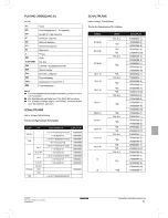
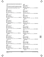
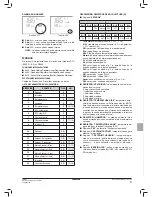
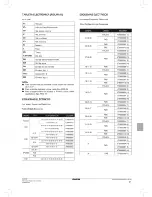
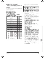
DESCRIPCIÓN REGISTROS DE SÓLO LECTURA [R]

■   

Registro 

“ESTADOS"

H

Bit 15

Bit 14

Bit 13

Bit 12

Bit 11

Bit 10

Bit 9

Bit 8

-

-

P04

Deshum

P06

P07

DI2

DI1

L

Bit 7

Bit 6

Bit 5

Bit 4

Bit 3

Bit 2

Bit 1

Bit 0

Vh

Vc

Alarma

MinT

Eco

P01

S/W

On/Off

- Tecla 

On/Off

: estado terminal (0 = Off, 1 = On)

S/W

: modalidad de funcionamiento (0: S = refrigeración, 

1: W = calefacción)

P01

: parámetro “instalación en la máquina/pared”

Eco

: lógica Economy activada

Min.T

: lógica Mínima Temperatura seleccionada

Alarma

: indicación general de alarma (se activa al aparecer 

una cualquiera de las alarmas gestionadas)

Vc

: estado salida digital Vc

Vh

: estado salida digital Vh

DI1

: valor lógico entrada dig. 1 (el estado físico de la 

entrada depende de la lógica asociada)

DI2

: valor lógico entrada dig. 2 (el estado físico de la 

entrada depende de la lógica asociada)

P07

: parámetro “Lógica DIN 2”

P06

: parámetro “Lógica DIN 1”

Deum

: deshumidi

fi

 cación en función (0: no, 1: sí)

P04

: parámetro “sonda agua presente”

■   

REGISTRO “VELOCIDAD”

: velocidad a la cual está fun-

cionando el terminal

-  0: ninguna ventilación activada
-  1: velocidad súper mínima
-  2: Velocidad mínima
-  3: Velocidad mediana
-  4: Velocidad máxima

■   

REGISTRO “TEMPERATURA AIRE”

: temperatura ambi-

ente leída desde el mando y mostrada en display (NOTA. 
Esta temperatura corresponde a la lectura efectuada por 
la sonda remota si el mando se encuentra en la máquina 
mientras que, en caso de que el mando esté instalado en 
la pared y la sonda remota esté desconectada, la lectura 
es efectuada por la sonda interna)

■   

REGISTRO “HUMEDAD”

: humedad ambiente leída 

desde el mando por la sonda relativa a la de temperatura 
utilizada

■   

REGISTRO “TEMPERATURA AGUA”

: temperatura del 

agua leída por la respectiva sonda (SW)

■   

Registro 

“P00”

 : parámetro “Con

fi

 guración mando”

■   

Registro 

“T. SETPOINT ACTIVO”

 : setpoint utilizado para 

efectuar la regulación

■   

Registro 

“T. SETPOINT USUARIO”

 : setpoint progra-

mado por el usuario (podría alejarse del setpoint activo 
como consecuencia de correcciones para lógicas de 
economy,…o para utilización del setpoint de super-
visión)

■   

Registro 

“VERSIÓN LCD”

: de

fi

 ne el tipo de mando y la 

versión software instalada (0xHHSS: HH: carácter ASCII, 
SS: versión sw)

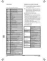
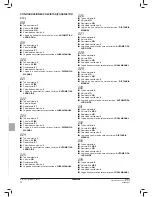
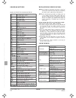
ALARMAS NO GRAVES

■   

Cód. 

A03 

= error sonda de temperatura del agua

■   

Cód. 

A04 

= error sonda humedad externa (sólo si está 

instalada la sonda remota de temperatura)

■   

Cód. 

A05 

= error sonda humedad interna

 NOTA.

  La indicación del código de alarma se vuelve visible 

sólo con termostato apagado.

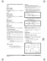
MODBUS

El protocolo implementado en el mando es el Modbus RTU 
(9600, N, 8, 2) en RS485

FUNCIONES IMPLEMENTADAS

■   

0x03 : Read Holding Registers (Leer Registros de Memoria)

■   

0x04 : Read Input Registers (Leer Registros de Entrada)

■   

0x10 : Write Multiple registers (Escribir Registros Múltiples) 

EXCEPCIONES IMPLEMENTADAS

Código de Excepción 02: Invalidar dirección de datos

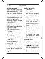
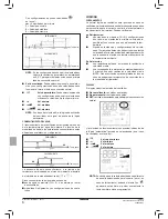
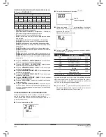
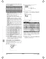
LISTA DE PARÁMETROS DE SUPERVISIÓN

DIRECCIÓN

REGISTRO

TIPO

U.M.

0

Estados

R

-

1

Velocidad

R

-

2

Temperatura aire

R

[°C/10]

3

Humedad

R

%

4

Temperatura agua

R

[°C/10]

5

P00: 

Con

fi

 guración

R

-

6

P05: 

Con

fi

 g. DIN

R

-

7

T. Setpoint activo

R

[°C/10]

8

T. Setpoint usuario

R

[°C/10]

9

Versión LCD

R

-

50

Digitales 1

R/W

-

51

 - 

R/W

-

52

Setpoint - Refrigeración

R/W

[°C/10]

53

Setpoint - Calefacción

R/W

[°C/10]

54

Mínimo Setpoint – Refr. 

R/W

[°C/10]

55

Máximo Setpoint – Refr.

R/W

[°C/10]

56

Mínimo Setpoint – Calef. 

R/W

[°C/10]

57

Máximo Setpoint – Calef.

R/W

[°C/10]

58

Velocidad

R/W

-

59

Corrección Economy

R/W

[°C/10]

Termostato  OFF

Termostato  ON

Summary of Contents for FWEC2

Page 1: ...LCD STEUERUNG F R TERMINALS Manual de instalaci n y de uso FWEC2 MANDO LCD PARA TERMINALES Manual de instala o e de uso FWEC2 COMANDO LCD PARA TERMINAIS Handleiding voor gebruik en onderhoud FWEC2 LC...

Page 2: ...1 2 5 3 4...

Page 3: ...8 9 6 7...

Page 4: ...NOTES...

Page 5: ...funzione economy da remoto logica contatto vedi parametri configurazione scheda sonda remota di temperatura per l acqua accessorio sonda di temperatura interna sonda di umidit interna sonda remota di...

Page 6: ...gitali 1 e 2 0 DIN1 DIN2 1 DIN1 DIN2 OnOff 2 DIN1 Est Inv DIN2 3 DIN1 Eco DIN2 4 DIN1 Est Inv DIN2 On Off 5 DIN1 Eco DIN2 On Off 6 DIN1 Est Inv DIN2 Eco P06 logica di utilizzo ingresso digitale 1 0 ap...

Page 7: ...ocit ventilazione 3 Logica commutazione estate inverno LOCALE MANUALE 008 Tubi impianto 2 Valvola NO Resistenza SI Velocit ventilazione 3 Logica commutazione estate inverno DISTANZA MANUALE 009 Tubi i...

Page 8: ...o 4 Valvola NO Resistenza NO Velocit ventilazione 3 Logica commutazione estate inverno LOCALE MANUALE 026 Tubi impianto 4 Valvola NO Resistenza NO Velocit ventilazione 3 Logica commutazione estate inv...

Page 9: ...ra a terra solo ad una estremit ____________________________________________________________ ATTENZIONE Utilizzare cavo schermato AWG24 Colori suggeriti per la rete di comunicazione A colore Marrone B...

Page 10: ...olari situazioni di forzatura che possono essere necessarie per il corretto controllo della temperatura o funzionamento del terminale Si possono avere In Raffreddamento con comando a bordo macchina P0...

Page 11: ...a selezionabile a termostato spento con la pressione contemporanea dei tasti La stessa combinazione di tasti disattiva tale funzionamento ATTIVAZIONE Se tale controllo selezionato il terminale si acce...

Page 12: ...o di temperatura molto superiore al set impostato alla media velocit Dovendo portare l umidit al valore impostato la ventilazione e la valvola se presente verr attivata anche nel caso in cui la temper...

Page 13: ...P01 parametro installazione bordo parete Eco logica Economy attiva Min T logica Minima Temperatura selezionata Allarme indicazione generale di allarme si attiva al manifestarsi di uno qualsiasi degli...

Page 14: ...oint in raffreddamento Registro MASSIMO SETPOINT RAFFR limite superiore per setpoint in raffreddamento Registro MINIMO SETPOINT RISC limite inferiore per setpoint in riscaldamento Registro MASSIMO SET...

Page 15: ...emota SW Sonda acqua SA Sonda aria remota DI1 Ingresso dig 1 CI12 Comune DI1 2 DI2 Ingresso dig 2 NB Per collegamenti di potenza utilizzare cavo sezione 1 mm2 Per ingressi digitali utilizzare cavo tip...

Page 16: ...muovere con cautela la pel licola protettiva del display la rimozione della pellicola pu provocare la comparsa di aloni scuri sul display che scompaiono dopo alcuni secondi e non sono indi ce di difet...

Page 17: ...contact for remote enabling of the economy mode contact logic see circuit board configuration pa rameters remote water temperature probe accessory FWTSKAA built in temperature probe built in humidity...

Page 18: ...uts 1 and 2 0 DIN1 DIN2 1 DIN1 DIN2 OnOff 2 DIN1 Sum Win DIN2 3 DIN1 Eco DIN2 4 DIN1 Sum Win DIN2 On Off 5 DIN1 Eco DIN2 On Off 6 DIN1 Sum Win DIN2 Eco P06 logic for use of digital input 1 0 open clos...

Page 19: ...ve NO Electrical heater YES Fan speed 3 Summer winter switching logic LOCAL MANUAL 008 System pipes 2 Valve NO Electrical heater YES Fan speed 3 Summer winter switching logic REMOTE MANUAL 009 System...

Page 20: ...er NO Fan speed 3 Summer winter switching logic LOCAL MANUAL 026 System pipes 4 Valve NO Electrical heater NO Fan speed 3 Summer winter switching logic REMOTE MANUAL 027 System pipes 4 Valve NO Electr...

Page 21: ...at one end only ____________________________________________________________ WARNING Use a shielded cable AWG24 Colours suggested for the communication network A Brown B Yellow _______________________...

Page 22: ...ed in particular override situations that may be necessary to ensure correct control of the temperature or the unit s operation This may occur in the cooling mode on board controller P01 0 and configu...

Page 23: ...ou can select the minimum temperature control by pressing at the same time the keys The same key combination disables this function ACTIVATION If this control is selected the unit will switch on when...

Page 24: ...temperature is much higher than the setpoint at medium speed In order to bring the humidity to the set value the fan and valve if present will be activated even if the room temperature has already rea...

Page 25: ...ed parameter Eco Economy logic active Min T Minimum Temperature logic selected Alarm general alarm indication activated when any of the managed alarms is triggered Vc status of digital output Vc Vh st...

Page 26: ...keypad lock 0 unlocked 1 locked En On Off enabling of On Off control via supervision system En S W enabling of mode control via supervision system En RE enabling of selection of electrical heater fun...

Page 27: ......

Page 28: ...ctive film from the display removal of the film may cause some dark streaks to appear on the display but these will disappear after a few seconds and are not signs of a controller defect INSTRUCTIONS...

Page 29: ...economy distance logique contact voir les param tres de confi guration de la carte sonde de temp rature loign e pour l eau accessoire sonde de temp rature interne sonde d humidit interne sond de temp...

Page 30: ...contr ler en modifiant des param tres donn s LISTE DES PARAM TRES P00 configuration commande voir Configurations Pr vues pour s lectionner le type d unit terminale contr ler P01 type d installation de...

Page 31: ...Vanne 2 3 VOIES R sistance NON Vitesse ventilation 4 Logique s lection t hiver DISTANCE MANUELLE CONFIGURATIONS PR VUES PARAM TRE P00 La commande LCD peut tre configur e de fa ons diff rentesselonlet...

Page 32: ...LE 035 Tuyaux installation 4 Vanne 2 3 VOIES R sistance NON Vitesse ventilation 4 Logique s lection t hiver DISTANCE MANUELLE CONFIGURATIONS PR VUES PARAM TRE P00 018 Tuyaux installation 2 Vanne 2 3 V...

Page 33: ...vitesse minimum 2 vitesse moyenne 3 vitesse maximum CONFIGURATIONS PR VUES PARAM TRE P00 036 Tuyaux installation 4 Vanne 2 3 VOIES R sistance NON Vitesse ventilation 4 Logique s lection t hiver AUTOM...

Page 34: ...nd by Vit extra minimum Vit minimum Vit moyenne Vit maximum NB si la vitesse activ e ne correspond pas la vitesse s lectionn e par l utilisateur cas de for age la premi re pression de la toucheo Fan e...

Page 35: ...ure Minimum appuyer simultan ment sur les touches le thermostat tant teint Pour d sactiver le fonctionnement utiliser la m me combinaison des touches ACTIVATION Si cette fonction est s lectionn e l un...

Page 36: ...que MONITEUR Le moniteur affiche les informations suivantes Contr le Temp rature Minimum s lectionn symbole Contr le Temp rature Minimum d clench indication DEFR D SHUMIDIFICATION La fonction de d shu...

Page 37: ...RE HUMIDIT humidit ambiante lue par la sonde correspondant la temp rature utilis e REGISTRE TEMP RATURE EAU temp rature de l eau lue par la sonde correspondante SW Registre P00 param tre Configuration...

Page 38: ...ion contr le temp rature Minimum depuis supervision Lock blocage clavier 0 non bloqu 1 bloqu En On Off autorisation contr le On Off depuis supervision En S W autorisation contr le modalit depuis super...

Page 39: ......

Page 40: ...niteur Des aur oles sombres pourraient appara tre sur le moniteur qui dispara tront au bout de quelques secondes Elles n indiquent pas la pr sence de d fauts INSTRUCTIONS DE MONTAGE MURAL 1 Retirer la...

Page 41: ...eKonfigurationsparameter Platine einen spannungsfreien Kontakt f r die Ferneinschaltung derEconomy Funktion Kontaktlogik sieheKonfigurations parameter Platine eine externe Temperatursonde f r das Wass...

Page 42: ...Konfigurierung Steuerung siehe Vorgesehene Konfigurationen f r die Wahl des zu steuernden Terminaltyps P01 Installationsart der Steuerung 000 am Terminal 001 Wand P02 Modbus Adresse um die nderung die...

Page 43: ...nd NEIN L ftungsgeschwindigkeit 4 UmschaltlogikSommer Winter FERNSTEUERUNGVON HAND VORGESEHENE KONFIGURATIONEN PARAMETER P00 Die LCD Steuerung kann je nach Systemtyp auf verschiedene Arten konfigurier...

Page 44: ...schwindigkeit 3 Umschaltlogik Sommer Winter AUTOMATISCHE LUFTSEITE 034 Rohrzahl Anlage 4 Ventil 2 3 WEGE Widerstand NEIN L ftungsgeschwindigkeit 4 Umschaltlogik Sommer Winter LOKALE VON HAND VORGESEHE...

Page 45: ...P00 035 Rohrzahl Anlage 4 Ventil 2 3 WEGE Widerstand NEIN L ftungsgeschwindigkeit 4 UmschaltlogikSommer Winter FERNSTEUERUNGVON HAND 036 Rohrzahl Anlage 4 Ventil 2 3 WEGE Widerstand NEIN L ftungsgesc...

Page 46: ...tlere Geschw Maximale Geschw Anm Wenn die momentane Geschwindigkeit anders ist alsdievomBenutzergew hlte beiZwangsschaltung wird bei einem ersten Dr cken der Taste Fan die gew hlte Geschwindigkeit ang...

Page 47: ...iese Betriebsart auch ausgeschaltet EINSCHALTUNG Wenn diese Kontrolle gew hlt wird schaltet sich das Terminal ein wenn die Raumtemperatur unter 9 C absinkt VENTIL Die Steuerung kann 2 oder 3 Wege Vent...

Page 48: ...zeigt Steuerung Mindesttemperaturkontrolle gew hlt Symbol Steuerung Mindesttemperaturkontrolle aktiv Meldung DEFR ENTFEUCHTUNG Die Entfeuchtungsfunktion die nur im K hlbetrieb anwendbar ist l sst das...

Page 49: ...g keit die die Steuerung von der mit der benutzten Tem peratursonde gekoppelten Sonde abliest REGISTER WASSERTEMPERATUR Von der entspre chenden Sonde abgelesene Wassertemperatur SW Register P00 Parame...

Page 50: ...wachung Eco Einschaltung Economy von berwachung MinT Einschaltung Mindesttemperaturkontrolle von berwachung Lock Sperre Tastatur 0 nicht gesperrt 1 gesperrt En On Off Freigabe On Off Kontrolle von ber...

Page 51: ......

Page 52: ...ung Anm Vor der Installation vorsichtig die Schutzfolie vom Display abziehen nach Abziehen der Folie k nnen dunkle R nder auf dem Display erscheinen die nach einigen Sekunden verschwinden und kein Zei...

Page 53: ...taci n de la funci n economy desde remoto l gica contacto ver par metros de confi guraci n de la tarjeta sonda remota de temperatura para el agua accesorio sonda de temperatura interna sonda de humeda...

Page 54: ...i n de algunos par metros es posible configurar la tarjeta en funci n del tipo de terminal sistema que deba gestionar LISTA DE PAR METROS P00 configuraci n mando ver Configuraciones Previstas para sel...

Page 55: ...encia NO Velocidad ventilaci n 4 L gica de conmutaci n verano invierno DISTANCIA MANUAL CONFIGURACIONESPREVISTAS PAR METRO P00 ElmandoLCDpuedeserconfiguradodediferentesmodosseg n el tipo de sistema La...

Page 56: ...gica de conmutaci n verano invierno AUTOM TICA LADO AIRE 034 Tubos sistema 4 V lvula 2 3 V AS Resistencia NO Velocidad ventilaci n 4 L gica de conmutaci n verano invierno LOCAL MANUAL CONFIGURACIONESP...

Page 57: ...PAR METRO P00 035 Tubos sistema 4 V lvula 2 3 V AS Resistencia NO Velocidad ventilaci n 4 L gica de conmutaci n verano invierno DISTANCIA MANUAL 036 Tubos sistema 4 V lvula 2 3 V AS Resistencia NO Vel...

Page 58: ...TA En caso de que la velocidad activada sea diferente de aquella seleccionada por el usuario por ej en caso de forzamiento pulsando la tecla Fan aparecer esta ltima al pulsar nuevamente la tecla cambi...

Page 59: ...eleccionarse con el termostato apagado pulsando simult neamente las teclas La misma combinaci n de teclas permite desactivar este funcionamiento ACTIVACI N Si dicho control est seleccionado el termina...

Page 60: ...MONITOR El monitor muestra las siguientes informaciones Control M nima Temperatura seleccionado s mbolo Control M nima Temperatura activado indicaci n DEFR DESHUMIDIFICACI N Lafunci ndedeshumidificaci...

Page 61: ...esde el mando por la sonda relativa a la de temperatura utilizada REGISTRO TEMPERATURA AGUA temperatura del agua le da por la respectiva sonda SW Registro P00 par metro Configuraci n mando Registro T...

Page 62: ...ma Temperatura desde supervisi n Lock bloqueo teclado 0 no bloqueado 1 bloqueado En On Off habilitaci n control On Off desde supervisi n En S W habilitaci n control modalidad desde supervisi n En RE h...

Page 63: ......

Page 64: ...isplay esta operaci n puede provocar la aparici n de aureolas oscuras en el display que desaparecen despu s de algunos segundos y no significan que el mando sea defectuoso INSTRUCCIONES PARA EFECTUAR...

Page 65: ...ica do contacto ver par metros de configura o da placa sonda remota de temperatura da gua acess rio sonda de temperatura interna sonda de humidade interna sondaremotadetemperaturadoar acess rio estaso...

Page 66: ...metros LISTA DOS PAR METROS P00 configura o do comando ver Configura es Previstas para seleccionar o tipo de terminal a gerir P01 tipo de instala o do comando 000 no terminal 001 de parede P02 endere...

Page 67: ...sist ncia N O Velocidade de ventila o 4 L gica da selec o ver o inverno DIST NCIA MANUAL CONFIGURA ESPREVISTAS PAR METROP00 O comando LCD pode ser configurado de v rios modos dependendo do tipo de sis...

Page 68: ...da instala o 4 V lvula 2 3 VIAS Resist ncia N O Velocidade de ventila o 4 L gica da selec o ver o inverno DIST NCIA MANUAL CONFIGURA ESPREVISTAS PAR METROP00 018 Tubos da instala o 2 V lvula 2 3 VIAS...

Page 69: ...m xima CONFIGURA ESPREVISTAS PAR METROP00 036 Tubos da instala o 4 V lvula 2 3 VIAS Resist ncia N O Velocidade de ventila o 4 L gica da selec o ver o inverno AUTOM TICA LADO AR 037 Tubos da instala o...

Page 70: ...and by Vel superm nima Vel m nima Vel m dia Vel m xima Nota se a velocidade activa for diferente daquela selec cionada pelo utilizador em caso de for amento a primeira press o da tecla Fan mostra esta...

Page 71: ...ra M nima pode ser seleccionado com o termostato desligado pela press o simult nea das teclas A mesma combina o de teclas desactiva esse funciona mento ACTIVA O Se esse controlo for seleccionado o ter...

Page 72: ...do pela entrada digital inibe essa l gica MONITOR O monitor mostra as seguintes informa es Controlo Temperatura M nima seleccionado s mbolo Controlo Temperatura M nima activo indica o DEFR DESUMIDIFIC...

Page 73: ...interna REGISTRO HUMIDADE umidade ambiente lida pelo comando da sonda relativa da temperatura usada REGISTRO TEMPERATURA DA GUA temperatura da gua lida pela respectiva sonda SW Registro P00 par metro...

Page 74: ...En On Off habilita controlo On Off a partir do supervisor En S W habilita controlo modalidade a partir do supervisor En RE habilita selec o Resist ncia El ctrica a partir do supervisor En ECO habilit...

Page 75: ......

Page 76: ...s Nota antes de instalar remova com cuidado a pel cula protetora do monitor ao remover a pel cula podem aparecer algumas manchas no monitor que desapa recem alguns segundos depois e n o significam que...

Page 77: ...ters configuratie kaart remote watertemperatuurmeter accessoire interne temperatuurmeter interne vochtigheidsmeter remote luchttemperatuurmeter accessoire deze meter indien aanwezig wordt gebruikt in...

Page 78: ...van een aantal parameters LIJST PARAMETERS P00 configuratiebediening zie VoorzieneConfiguraties om het soort te besturen terminal te selecteren P01 soort installatie van de bediening 000 op de termina...

Page 79: ...ventilatie 4 Logica commutatie zomer winter AFSTAND HANDMATIG VOORZIENE CONFIGURATIES PARAMETER P00 DeLCDbedieningkannaaraanleidingvanhetsysteemtypeop verschillende wijzes geconfigureerd worden De ve...

Page 80: ...e 3 Logica commutatie zomer winter AUTOMATISCH ZIJDE LUCHT 034 Slangen installatie 4 Klep 2 3 WEGS Weerstand NEE Snelheid ventilatie 4 Logica commutatie zomer winter PLAATSELIJK HANDMATIG VOORZIENE CO...

Page 81: ...S PARAMETER P00 035 Slangen installatie 4 Klep 2 3 WEGS Weerstand NEE Snelheid ventilatie 4 Logica commutatie zomer winter AFSTAND HANDMATIG 036 Slangen installatie 4 Klep 2 3 WEGS Weerstand NEE Snelh...

Page 82: ...um snelh gemiddelde snelh maximum snelh NB in het geval dat de geactiveerde snelheid verschilt van de door de gebruiker gekozen snelheid in het geval van een forcering wordt met een enkele druk op de...

Page 83: ...men KEUZE De controle Minimum Temperatuur kan geselecteerd worden bij uitgeschakelde thermometer door de druk tegelijkertijd op de toetsen Dezelfde combinatie van toetsen deactiveert deze functionerin...

Page 84: ...nformatie weer controle Minimum Temperatuur geselecteerd symbool controle Minimum Temperatuur actief weergave DEFR ONTVOCHTING De ontvochtingsfunctie alleen te gebruiken in de afkoelmo daliteit voorzi...

Page 85: ...omgevingsvochtigheid gemeten door de bediening van de meter met betrekking tot de gebruikte temperaturmeter meter REGISTER WATERTEMPERATUUR watertemperatuur gemeten door de desbetreffende meter SW Re...

Page 86: ...MinT activering controle Minimum Temperatuur voor supervisie Lock blokkering toetsenbord 0 niet geblokkeerd 1 geblokkeerd En On Off activering controle On Off voor supervisie En S W activering contro...

Page 87: ......

Page 88: ...orzichtigdebeschermende film van het display De verwijdering van de film zou de vorming van vlekken op het display kunnen veroorzaken die na een aantal seconden verdwijnen en die geen aanwijzing voor...

Page 89: ...s param terek tiszta rintkez a kihelyezett economy funkci enged lyez s hez rintkez logika l sd k rtya konfigur ci s param terek kihelyezett v z h m rs kletm r szonda tartoz k bels h m rs kletm r szond...

Page 90: ...lapj n n h ny param ter m dos t sa tj n PARAM TEREK LIST JA P00 vez rl konfigur ci ja l sd El rtKonfigur ci k az ir ny tand termin l t pus nak kiv laszt s hoz P01 a vez rl beszerel si t pusa 000 termi...

Page 91: ...2 Szelep 2 3 utas F t elem nincs Ventill ci s sebess g 4 Ny r t l tkapcsol logika t voli K ZI EL RT KONFIGUR CI K P00 PARAM TER AzLCDvez rl tarendszert pusaalapj nk l nf lem dokban lehet konfigur lni...

Page 92: ...entill ci s sebess g 3 Ny r t l tkapcsol logika AUTOMATIKUS LEVEG oldalon 034 Berendez s cs vei 4 Szelep 2 3 utas F t elem nincs Ventill ci s sebess g 4 Ny r t l tkapcsol logika helyi K ZI EL RT KONFI...

Page 93: ...cs vei 4 Szelep 2 3 utas F t elem nincs Ventill ci s sebess g 4 Ny r t l tkapcsol logika t voli K ZI 036 Berendez s cs vei 4 Szelep 2 3 utas F t elem nincs Ventill ci s sebess g 4 Ny r t l tkapcsol lo...

Page 94: ...an l v ventill tor eset n Szuperminimum seb Minimum seb K zepes seb Maximum seb MEGJ amennyiben az akt v sebess g k l nb zik a felhasz n l ltal kiv lasztott sebess gt l k nyszerm k d s eset n a Fanbil...

Page 95: ...sk nt a F t s m dban kiv lasztott k KIV LASZT S A Minimum H m rs klet ellen rz s kiv laszthat kikapcsolt termoszt t mellett a billenty k egyidej benyo m s val Ugyanaz a billenty kombin ci kikapcsolja...

Page 96: ...m ci kat jelen ti meg Kiv lasztott Minimum H m rs klet ellen rz s jel Akt v Minimum H m rs klet ellen rz s DEFR jel l s P R TLAN T A csak h t si zemm dban haszn lhat p r tlan t funkci lehet v teszi a...

Page 97: ...regisztr l s aszondavez rl je ltalleolva sott k rnyezeti p ratartalom a felhaszn lt h m rs kletre vonatkoz an V z h m rs klet regisztr l s a vonatkoz szonda SW ltal leolvasott v z h m rs klet P00 reg...

Page 98: ...l s kiv laszt sa Eco fel gyel Economy aktiv l sa MinT fel gyel Minimum H m rs klet ellen rz s aktiv l sa Lock billenty zet reteszel se 0 nem reteszelt 1 reteszelt En On Off fel gyel On Off ellen rz s...

Page 99: ......

Page 100: ...g tt kell elhelyezni MEGJ a felszerel s el tt vatosan t vol tsa el a display r l a v d f li t af liaelt vol t sas t tfoltokmegjelen s t v lthatja ki a display en amelyek n h ny m sodperc ut n elt nnek...

Page 101: ...EC2 Advanced electronic controller FC66002764 LCD Galletti 1 Master Slave 247 bus RS485 2 255 1 2 Set point 2 C on off On Off ON OFF economy LCD 2 1 2 3 ON OFF Off AUTO Economy 3 On Off Up Down 5 0 30...

Page 102: ...ff On P00 P01 000 001 P02 Modbus 0 1 247 255 P03 20 50 C 10 P04 0 1 P05 1 2 0 DIN1 DIN2 1 DIN1 DIN2 On Off 2 DIN1 DIN2 3 DIN1 Eco DIN2 4 DIN1 DIN2 On Off 5 DIN1 Eco DIN2 On Off 6 DIN1 DIN2 Eco P06 1 0...

Page 103: ...Advanced electronic controller FC66002764 009 2 3 010 2 4 011 2 4 012 2 4 013 2 2 3 3 014 2 2 3 3 015 2 2 3 3 016 2 2 3 4 017 2 2 3 4 P00 LCD P00 001 2 3 002 2 3 003 2 3 004 2 4 005 2 4 006 2 4 007 2...

Page 104: ...vanced electronic controller FC66002764 026 4 3 027 4 3 028 4 4 029 4 4 030 4 4 031 4 2 3 3 032 4 2 3 3 033 4 2 3 3 034 4 2 3 4 P00 018 2 2 3 4 019 2 3 3 020 2 3 3 021 2 3 3 022 2 3 4 023 2 3 4 024 2...

Page 105: ...Set ZN P03 3 4 Fan 3 1 2 3 P00 035 4 2 3 4 036 4 2 3 4 037 4 3 038 4 4 RS485 Bus 2 RS485 A B GND AWG 24 0 511 4 Master Slave 1 A B 2 ____________________________________________________________ AWG24...

Page 106: ...6 FWEC2 Advanced electronic controller FC66002764 P01 0 10 2 2 On standby On OFF stand by 4 sm 1 2 3 4 0 5 C 4 4 o P04 0 4 NO NO...

Page 107: ...7 FWEC2 Advanced electronic controller FC66002764 ECONOMY Economy setpoint 2 5 C set 2 5 C set 2 5 C Economy 9 C 2 3 ON OFF 230 V set 3 Sel ON OFF...

Page 108: ...8 FWEC2 Advanced electronic controller FC66002764 Off A01 A02 10 C Off Off DEFR 10 P04 0 P08 0 5 10 40 30 3...

Page 109: ...P00 T SETPOINT setpoint T SETPOINT setpoint setpoint economy setpoint LCD 0xHHSS HH ASCII SS sw A03 A04 A05 MODBUS Modbus RTU 9600 N 8 2 RS485 0x03 Read Holding Registers 0x04 Read Input Registers 0x1...

Page 110: ...RE En S W En On Off L Bit 7 Bit 6 Bit 5 Bit 4 Bit 3 Bit 2 Bit 1 Bit 0 Lock MinT Eco RE S W On Off On Off On Off S W 0 1 RE Eco Economy MinT Lock 0 1 En On Off On Off En S W En RE En ECO economy En Mi...

Page 111: ......

Page 112: ...S Flap DI1 1 DI2 2 CI12 A B GND RS 485 F IL CN RHC EXT ON OFF EPIMB6 4 EPIB6 FWD M VHC VC VH TSA TSM SC ECONOMY COMFORT ECONOMY 1 8 2 503 3 5x8 9 4 5 1 90 250Vac 50 60 8 500mA Range 0 50 C Range 10 60...

Page 113: ...slave bus RS485 2 master 255 slave 1 1 4 1 2 Set point 6 Slave 6 2 C Setpoint master ON OFF 7 6 6 ON OFF 7 1 6 4 1 9 1 1 1 ON OFF 6 6 4 1 9 6 economy 6 6 LCD LCD 2 1 9 6 2 6 3 ON 6 6 6 OFF OFF AUTO 1...

Page 114: ...0 6 6 7 P01 000 001 P02 Modbus 6 1 0 1 247 Slave 255 Master P03 D 20 50 C 10 6 1 P04 0 6 1 6 D P05 1 2 0 DIN1 DIN2 1 DIN1 DIN2 OnOff 2 DIN1 C DIN2 3 DIN1 Eco DIN2 4 DIN1 C DIN2 On Off 5 DIN1 Eco DIN2...

Page 115: ...010 2 6 1 4 6 011 2 6 1 4 6 012 2 6 1 4 6 013 2 6 2 3 1 3 6 014 2 6 2 3 1 3 6 015 2 6 2 3 1 3 6 016 2 6 2 3 1 4 6 017 2 6 2 3 1 4 6 0 56 P00 LCD 00 6 001 2 6 1 3 6 002 2 6 1 3 6 003 2 6 1 3 6 004 2 6...

Page 116: ...027 4 6 1 3 6 028 4 6 1 4 6 029 4 6 1 4 6 030 4 6 1 4 6 031 4 6 2 3 1 3 6 032 4 6 2 3 1 3 6 033 4 6 2 3 1 3 6 034 4 6 2 3 1 4 6 0 56 P00 018 2 6 2 3 1 4 6 019 2 6 3 1 3 6 020 2 6 3 1 3 6 021 2 6 3 1 3...

Page 117: ...3 4 F C Fan 1 1 1 6 3 1 2 3 0 56 P00 035 4 6 2 3 1 4 6 036 4 6 2 3 1 4 6 037 4 6 1 3 6 038 4 6 1 4 6 6 RS485 Bus 2 RS485 GND AWG 24 0 511 mm 4 MASTER SLAVE 1 A B 2 D __________________________________...

Page 118: ...nced electronic controller FC66002764 1 A P01 0 6 6 6 6 10 2 6 6 1 2 1 1 6 1 D On 6 6 standby On OFF 1 stand by H 1 Fan D D 4 sm 1 2 3 4 6 6 1 0 5 C 4 H 4 7 1 D 1 D 6 6 6 6 P04 0 4 1 1 4 9 9 9 4HP 9 4...

Page 119: ...FC66002764 6 6 1 6 6 6 6 ECONOM Economy 6 setpoint 2 5 C 4 1 Set 2 5 C 9 Set 2 5 C D Economy 6 7 1 6 6 9 F 9 D 6 9 C 10 C OFF OFF 0 6 6 2 3 ON OFF 6 230 V 6 6 Set 7 3 6 6 1 9 1 1 1 6 1 6 1 1 6 6 6 1...

Page 120: ...controller FC66002764 6 6 OFF 6 1 6 6 6 6 D 6 6 H A01 1 A02 1 H A03 A04 1 D A05 1 D 6 1 9 6 9 1 DEFR 5 1 6 10 6 F 4 1 6 P04 0 D 08 0 D 6 D 5 F D 1 10 6 40 D 30 1 1 6 6 6 D 6 3 7 9 9 Codice allarme Te...

Page 121: ...3 4 6 6 D 6 D 6 6 D H 6 6 D 6 D SW 00 7 T Setpoint setpoint T Setpoint C setpoint D setpoint economy setpoint LCD D 0xHHSS HH ASCII SS MODBUS Modbus RTU 9600 N 8 2 RS485 0x03 Read Holding Registers 0...

Page 122: ...Off L Bit 7 Bit 6 Bit 5 Bit 4 Bit 3 Bit 2 Bit 1 Bit 0 Lock MinT Eco RE S W On Off ON OFF On Off S W 0 4 1 1 9 RE ECO Economy MinT 9 Lock 0 1 1 En On Off On Off En S W En RE En ECO economy En MinT 9 E...

Page 123: ......

Page 124: ...4 2 CI12 A B GND RS 485 F IL 7 CN RHC 4 1 9 EXT D ON OFF EPIMSB6 4 EPIB6 FWD M VHC 6 6 4 1 9 VC 6 6 4 1 VH 6 6 9 TSA TSM 9 SC ECONOMY D Comfort Economy 6 1 D 1 1 6 C 8 2 503 6 3 7 5x8mm 6 6 6 6 1 C 9...

Page 125: ...NOTES...

Page 126: ......

Page 127: ...FC66002557 UT66000887 3 4...

Page 128: ...UT66000888 UT66000889 5 6...

Page 129: ......

Page 130: ......

Page 131: ......

Page 132: ...Zandvoordestraat 300 B 8400 Oostende Belgium FC66002764...

Reviews: