FWEC2
Advanced electronic controller
Installation and
operation manual
Installation and operation manual
1
FWEC2
Advanced electronic controller
FC66002764
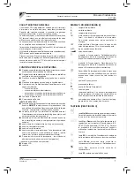
GENERAL CHARACTERISTICS
LCD controller has been designed to manage the operation of
indoor units with single-phase multispeed asynchronous motor.
Compared to the standard model it has the added features of
advanced humidity control and serial communication.
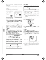
This controller allows to set (
fi
gure 1) up a Master-Slave system
(up to 247 slave terminals), in which one of the Microproces-
sor controllers plays the role of Master and controls all of the
other slave elements.
In this case as well the connection is made via an RS485 bus,
consisting of a simple shielded 2-conductor cable.
The master (identi
fi
ed by the address 255) sends the following
information to the slave controllers:
(1)
Operating mode (Cooling or Heating)
(2)
Setpoint for room temperature.
The speed selector of each slave controller remains enabled
and the room temperature can be adjusted within a range of
± 2°C around the setpoint value transmitted by the master
controller.
MAIN FUNCTIONS AND FEATURES:
■
Air temperature adjustment through automatic variation
of fan speed;
■
Regulation of air temperature via fan
on-off
control (fan
runs at a
fi
xed speed),
■
Control of
On-Off
valves for two or four-pipe systems
■
Control of electrical heater for auxiliary heating.
■
Cooling/heating switching in the following modes:
- local manual switching
- remote, manual (centralised);
- automatic, depending on water temperature
- automatic, depending on air temperature
■
Dehumidify Function
■
Serial Communication
ADDITIONAL FEATURES INCLUDE:
■
no-voltage contact for external activation (e.g. window
contact, remote
ON/OFF
, occupancy sensor, etc.) which
may enable or disable unit operation (contact logic: see
circuit board con
fi
guration parameters).
■
no-voltage contact for centralised remote Cooling/Heating
changeover (contact logic: see circuit board con
fi
guration
parameters).
■
no-voltage contact for remote enabling of the economy
mode (contact logic: see circuit board con
fi
guration pa-
rameters).
■
remote water temperature probe (accessory FWTSKAA)
■
built-in temperature probe
■
built-in humidity probe
■
remote air temperature probe (accessory FWTSKAA) (this
probe, if present, is used in place of the internal one for
the measurement of room temperature).
■
Remote humidity probe (accessory FWHSKAA - to be used
in combination with the remote temperature probe)
The control panel is composed of:
■
LCD display
■
key board
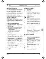
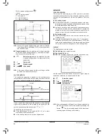
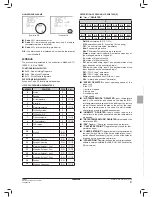
LCD DISPLAY (SEE FIGURE 2)
(1) room
temperature
(2) room
humidity
(3) set
temperature
ON
fan status. When
fl
ashing it indicates that fans are
off standing for a call from the thermostat. If the
symbol is steadily lit it means that the fans are
running
OFF
fan status. Fans are off as speed is set to Off or
the control is off.
AUTO
automatic ventilation logic
fan
speed
operation mode: Cooling. When
fl
ashing it indicates
that water circuit is not enabled to fan ventilation.
operation mode: Heating. When
fl
ashing it indicates
that water circuit is not enabled to fan ventilation.
Dehumidi
fi
cation. When
fl
ashing it indicates that
the circuit is not enabled to dehumidi
fi
cation. If the
symbol is steadily lit it means that the function is
active.
Economy option enabled
Alarm
triggered
Minimum Temperature Control
valve
open
electrical heater: If the symbol
fl
ashes it means that
the electrical heater is on; if steadily lit it means only
that the electrical heater has been selected
serial communication active. The
fl
ashing symbol
indicates that the controller is the master
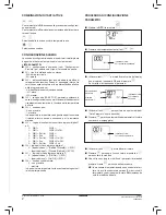
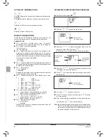
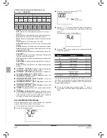
KEY BOARD (SEE FIGURE 3)
On/Off
key: Thermostat On/Off. During the proce-
dure of parameter modi
fi
cation, it permits to return
to normal operating conditions
Up
and
Down
keys: changing of thermostat set-
ting temperature (Heating:[5.0-30.0°C], Cooling:
[10.0-35.0°C]). During the procedure of parameter
modi
fi
cation, they are used to select the parameters
or to change their value
SEL
key: in the heating mode, the electrical heater
element can be selected as auxiliary function
Mode
key: selection of Heating/Cooling operating
mode
Fan
key: selection of operating speed
EC
key: selection of Economy mode
Summary of Contents for FWEC2
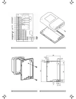
Page 2: ...1 2 5 3 4...
Page 3: ...8 9 6 7...
Page 4: ...NOTES...
Page 27: ......
Page 39: ......
Page 51: ......
Page 63: ......
Page 75: ......
Page 87: ......
Page 99: ......
Page 111: ......
Page 123: ......
Page 125: ...NOTES...
Page 126: ......
Page 127: ...FC66002557 UT66000887 3 4...
Page 128: ...UT66000888 UT66000889 5 6...
Page 129: ......
Page 130: ......
Page 131: ......
Page 132: ...Zandvoordestraat 300 B 8400 Oostende Belgium FC66002764...

