Indoor Unit
SiENBE04-401A
156
Removal Procedure
1.4
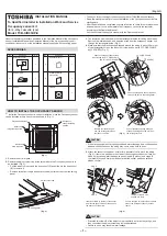
Removal of Electrical Box, PCB and Swing Motor
Procedure
Warning
Be sure to wait 10 minutes or more after turning off all power supplies
before disassembling work.
Step
Procedure
Points
Remove front grill.
1. Remove electrical box.
1
Disconnect the
connection wires.
2
Disconnect connectors
(S1 and S7) of fan
motor.
Pay attention to the direction
of the retainer of the
thermistor so that the
retainer will not touch the
harness (same as the
existing models.)
3
Disconnect one
connector (S6) of swing
motor.
4
Remove heat
exchanger thermistor.
Terminal board
Earth screw
Heat exchanger
thermistor
Swing motor
PC Board
S1
S7
S6
Plate of
connection
wires
(R2529)
Heat exchanger
thermistor
Retainer of
thermistor
S1
Fan motor
S7
Connector of
fan motor
S6
Connector of
swing motor
(R2530)
Summary of Contents for FTKS20CVMB
Page 19: ...List of Functions SiENBE04 401A 10 List of Functions...
Page 45: ...Specifications SiENBE04 401A 36 Specifications...
Page 81: ...Control Specification SiENBE04 401A 72 Function and Control...
Page 111: ...Instruction SiENBE04 401A 102 System Configuration...
Page 155: ...Check SiENBE04 401A 146 Service Diagnosis...
Page 225: ...Outdoor Unit RK X H C ARK X H C R Y N C SiENBE04 401A 216 Removal Procedure...
Page 229: ...Others SiENBE04 401A 220 Others...