


FCQG35~1 FCQHG71~140FVEB
Split System air conditioners
3P308369-1C – 2012.10
Installation manual
4
4
Check if the unit is horizontally levelled.
-
Do not install the unit tilted. The indoor unit is equipped with a
built-in drain pump and float switch. (If the unit is tilted against
the direction of the condensate flow (the drain piping side is
raised), the float switch may malfunction and cause water to
drip.)
-
Check if the unit is levelled at all four corners with a water
level or a water-filled vinyl tube as shown in
figure 12
.
5
Remove the paper pattern for installation. (For new ceilings
only.)
R
EFRIGERANT
PIPING
WORK
For refrigerant piping of outdoor unit, refer to the installation manual
supplied with the outdoor unit.
Execute heat insulation work completely on both sides of the gas
piping and liquid piping. Otherwise, this can sometimes result in
water leakage.
Before rigging tubes, check which type of refrigerant is used.
■
Use a pipe cutter and flare suitable for R410A refrigerant.
■
To prevent dust, moisture or other foreign matter from infiltrating
the tube, either pinch the end, or cover it with tape.
■
The outdoor unit is charged with refrigerant.
■
To prevent water leakage, execute heat insulation work
completely on both sides of the gas and liquid piping. When
using a heat pump, the temperature of the gas piping can reach
up to approximately 120°C, use insulation which is sufficiently
heat resistant.
■
Be sure to use both a spanner and torque wrench together when
connecting or disconnecting pipes to/from the unit.
■
Do not mix anything other than the specified refrigerant, such as
air, etc. inside the refrigerant circuit.
■
Only use annealed material for flare connections.
■
Refer to
Table 1
for the dimensions of flare nut spaces and the
appropriate tightening torque. (Overtightening may damage the
flare and cause leaks.)
Table 1
■
When connecting the flare nut, coat the flare inner surface with
ether oil or ester oil and initially tighten 3 or 4 turns by hand
before tightening firmly.
■
If the refrigerant gas leaks during the work, ventilate the area. A
toxic gas is emitted by the refrigerant gas being exposed to a
fire.
■
Make sure there is no refrigerant gas leak. A toxic gas may be
released by the refrigerant gas leaking indoor and being
exposed to flames from an area heater, cooking stove, etc.
■
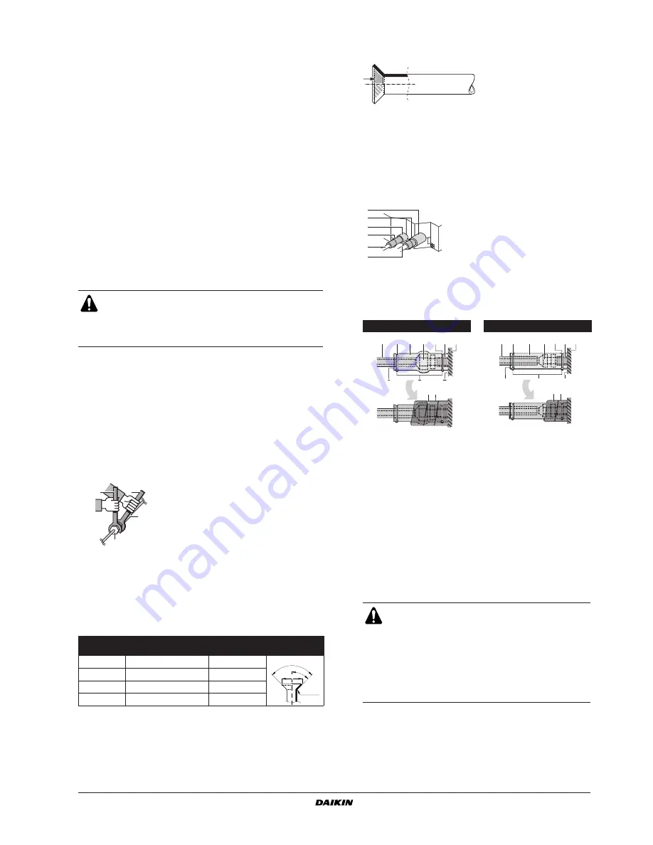
Finally, insulate as shown in the figure below (use the supplied
accessory parts)
Piping insulation procedure
1
Water level
2
Vinyl tube
Installation shall be done by a licensed refrigeration
technician, the choice of materials and installation shall
comply with the applicable national and international
codes. In Europe, EN378 is the applicable standard that
shall be used.
Pipe gauge
Tightening torque
Flare dimension
A (mm)
Flare shape
Ø6.4
15~17 N•m
8.7~9.1
Ø9.5
33~39 N•m
12.8~13.2
Ø12.7
50~60 N•m
16.2~16.6
Ø15.9
63~75 N•m
19.3~19.7
1
2
3
4
1
Torque wrench
2
Spanner
3
Piping union
4
Flare nut
R0.4~0.8
45
° ±
2
90
°±
2
A
Gas piping
Liquid piping
1
Piping insulation material (field supply)
2
Flare nut connection
3
Insulation for fitting (delivered with the unit)
4
Piping insulation material (main unit)
5
Main unit
6
Clamp (field supply)
7
Medium 1 sealing pad for gas piping (delivered with the unit)
Medium 2 sealing pad for liquid piping (delivered with the unit)
A
Turn seams up
B
Attach to base
C
Tighten the part other than the piping insulation material
D
Wrap over from the base of the unit to the top of the flare nut
connection
■
For local insulation, be sure to insulate local
piping all the way into the pipe connections inside
the unit.
Exposed piping may cause condensation or may
cause burns when touched.
■
Make sure that no oil remains on plastic parts of
the decoration panel (optional equipment).
Oil may cause degradation and damage to
plastic parts.
1
2
5
3
4
5
1
Liquid pipe
2
Gas pipe
3
Insulation for fitting for liquid
pipe
4
Insulation for fitting for gas
pipe
5
Clamps
(use 2 clamps per insulation)
A
B
D
C
7
1
2
3
4
5
6
6
A
B
C
1
2
3
4
5
6
6
D
7
Summary of Contents for FCQG100FVEB
Page 14: ......


