


Installation and operation manual
18
EWWD440~850AAYNNO**
Packaged water-cooled water chillers
4PW25558-1B
Checking the water system
■
Pump is filled with water
Fill the water piping, taking into account the minimum water
volume required by the unit. Refer to
Perform an air purge at the same time. Purging air is possible by
opening the airpurge valves on top of the condenser and
evaporator.
Operation with insufficient air purge can lead to drop of
performance.
■
Water pressure is less than the specified value
Check the chilled water side and condenser water side water
pressure.
Check the water pressure not only during normal flow, but also
at pump start.
If water pressure is over the maximum operating water pressure,
it may damage the machine.
In case of a standard model, the maximum operating water
pressure is 1.0 MPa both at chiller water side and condenser
water side.
■
No water leakage
Make sure that there is no water leakage from flanges or shells.
■
No mixing of air
Sound like "gobo gobo" while the water flows, or pressure
gauges attached to the equipment oscillate, or while the pump
operating current is unstable, means that air got mixed into the
water system.
Perform an air purge again.
Mixing of air not only makes the unit performance drop, but also
leads to damage of heat exchanger tubes inside the condenser
and evaporator.
■
Flow rate adjustment has been made
Adjust the flow rate to a proper rate using a flow meter and
adjust the rate in function of the pump characteristics chart.
Too low flow rate not only makes the unit performance drop, but
also leads to damage due to acceleration in adhesion of
contaminant and foreign matters to the heat exchanger tubes.
Excessive flow rate may lead to damage due to corrosion of heat
exchanger tubes.
■
Make adjustment of water interruption relay (Protective device)
Be sure to make this adjustment. Local adjustment to the head
of equipment is required.
Remove the cover of the water interruption relay to observe the
movement of the internal metal piece contact. Check that the
metal piece contact moves upward when the water flows
and moves downward during water flow failure. If the contact
has already moved upward during water flow failure, turn the
adjusting screw clockwise by means of a screwdriver so that the
contact moves as indicated in the drawing. If the contact does
not move upward while water flows, adjust it by turning the
adjusting screw counterclockwise.
Checking the unit body
■
Open all shut-off valves indicated by a red label: “OPEN THIS
VALVE BEFORE OPERATION”.
All stopvalves, except those for charging of refrigerant or
oil, must be opened prior to start of the unit. Be sure to
check that they stay opened.
Stopvalves given below are installed.
•
Oil charge valve and refrigerant charge valve are used under
normally closed condition.
•
The pressure gauge valve (discharge pressure/suction pressure)
is designed as a 3-way valve taking maintenance of the pressure
sensors into account. Do not fully open these valves but keep
them at an intermediate opening.
•
Valves other than described in the 2 points above, are used under
normally opened condition.
Checking the settings on the controller
■
Prior to putting the unit into operation, change the settings of the
graphic panel display to the details that meet your configuration.
Refer to
"Operating the graphic panel display" on page 12
"Functions of this model" on page 21
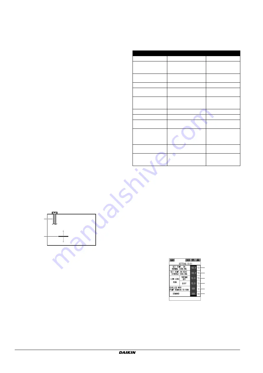
■
The “SETTING (1/2)” screen represented below is the one of a
model with 2-temperature setting option. In case of the standard
model, the target temperature to be set will be represented with
“SET TEMPERATURE”.
1
Adjusting screw
2
Metal piece contact
3
When water flows
4
During water flow failure
2
1
3
4
Installation position
Stopvalve shape
Comment
Suction piping
Suction stop valve
Important
Liquid piping (Bottom)
Copper pipe stopvalve
Important
EWWD440/600: 1 point
EWWD850:
2 points
Condenser top
(Right and left)
Copper pipe stopvalve (3/8")
2 points, right and left
Condenser top (Center)
Copper pipe stopvalve (3/8")
—
Copper pipe from
condenser to compressor
Packless valve (3/8")
2 points,
right and left
Compressor
discharge chamber
(Oil discharge valve)
Copper pipe stopvalve (3/8")
2 points, right and left
Use at normally closed
condition.
Float chamber top
Copper pipe stopvalve (3/8")
—
Float chamber
Packless valve (5/8")
—
Evaporator bottom
Copper pipe stopvalve (3/8")
3 points,
right and left
Liquid pipe
(Refrigerant charge valve)
Copper pipe stopvalve (3/8")
EWWD440/600: 1 point
EWWD850:
2 points
Use at normally closed
condition.
Copper pipe from
evaporator to suction pipe
Copper pipe stopvalve (3/8")
—
Pressure gauge valve
3-way stopvalve for copper
pipe (3/8")
2 points,
Be sure to use at
intermediate opening
1
Set the chilled water outlet temperature target value.
The standard model is an outlet temperature control-only
model.
2
Make settings for the low load stop function.
3
Set the remaining operating time of the pump.
In case of models with 2-temperature setting option, also the
cooling water pump uses this setting.
The setting valve shall be 360 seconds or more.
4
Make setting of the current demand control.
1
1
2
2
3
4


