background image


Installation and operation manual

16

EWWD440~850AAYNNO**

Packaged water-cooled water chillers

4PW25558-1B

Alarm history (“FAULTS”)
If the unit suffers abnormal stops, the alarm history pops up.
Both unit errors and compressor only errors are stored in the
history.

Unit error
Unit errors indicate a critical malfunction such as a discharge
high-pressure error or a chilled water overcool error that has
effect on the entire unit. Both compressors stop.

Individual compressor error
Individual compressor errors indicate the error of an individual
compressor such as a motor overload.
The alarm is indicated and the error-side compressor stops. The
compressor of the side where the error does not occur continues
to operate.

“FAULTS” screen (identical to the “WARNINGS” screen)

How to clear everything (total clear)

1

Touch the "ST" button.
A frame appears as if it encloses the uppermost message.

2

Touch the "ALL CLR" button to clear all events.

3

Touch the "END" button.

How to clear an individual event

1

Touch the "ST" button.
A frame appears as if it encloses the uppermost message.

2

Move the frame to the desired message using the "

"and "

"

buttons.

3

Touch the "CLR" button to erase the selected event.

4

Touch the "END" button.

Error resetting method

This chapter explains about how to reset errors in case the unit was
stopped.

As how to reset actions are listed in the graphic panel display,
resetting the error can be executed by doing as indicated.

For ensuring a proper error cause investigation however, we
recommend you to perform reset step by step as described below.

1

Solve the cause of error.
(If the solution is not performed correctly, “RESET” may not be
possible.)

2

In case of a unit error, push the unit error reset button on the
door of the switch box.

3

Touch the “RESET” button on the graphic display panel once.
The alarm buzzer stops.

4

Select the "HISTORY" screen through the "MENU" screen.

5

Select "OPE DATA WHEN ERROR OCCURRED" from the
"HISTORY" screen.

6

Record the listed 6 minutes data.

7

Return to the "MENU" screen.

8

Select the "ALARM" screen from the "MENU" screen.

9

Return to the above error occurrence screen.

10

Touch the “RESET” button once again to reset the error.

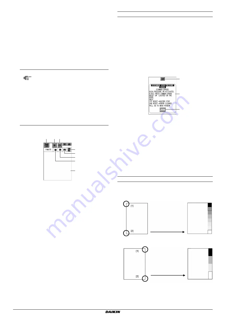
Adjusting the contrast and brightness of the screen

Adjustment of the contrast and brightness of the screen can be
performed as follows.

Adjustment of the contrast

Adjustment of the brightness

NOTE

In case of a unit error, history of details on
operational data of the last 6 minutes is
stored per minute in “OPE DATA WHEN
ERROR OCCURED”. These details are kept
in memory until completion of the error reset.
Record all details of the last 6 minutes
before resetting the error.

In case of an individual compressor error,
history on operational data is not recorded,
as the unit keeps running.

It is always possible to consult the last 6
minutes operational data per minute during
normal operation through this screen.

1

This is the button for jumping to the history menu.

2

Use these buttons when you want to see older data that does not 
appear on the the screen or when you erase data.

3

Use these buttons when you erase the data.

4

Use these buttons to scroll the data.

5

Indications of date and time when the error occurred and details of 
the error. History of 128 events in order of occurrence is kept in 
memory.
(*) Permanent power off for prolonged periods may result in 
memory to be cleared. (New models: 60 days, when lifetime of the 
graphic panel display battery expires: 6 days).

1

2

2

3

5

3
4
4

4~9

3+10

2

Touch the lower left corner of the 
screen [2] while touching the 
upper left corner [1] of the screen 
to activate the contrast 
adjustment mode. Select the 
contrast of your preference and 
touch any other part of the 
screen to exit this mode.

Touch the lower right corner of 
the screen [2] while touching the 
upper right corner [1] of the 
screen to activate the brightness 
adjustment mode. Select the 
brightness of your preference 
and touch any other part of the 
screen to exit this mode.

Summary of Contents for EWWD440AAYNNO series

Page 1: ...INSTALLATION AND OPERATION MANUAL EWWD440AAYNNO EWWD600AAYNNO EWWD850AAYNNO Packaged water cooled water chillers...

Page 2: ...03 Directives telles que modifi es 04 Richtlijnen zoals geamendeerd 05 Directivas seg n lo enmendado 06 Direttive come da modifica 07 v 08 Directivas conforme altera o em 09 10 Direktiver med senere...

Page 3: ...ue 36 Thank you for purchasing this Daikin air conditioner SAFETY CONSIDERATIONS For your safety and that of others observe the precautions listed here after at all time There are two types of precaut...

Page 4: ...ould result in a lack of oxygen in the latter case Make sure there is enough service space If the space is not enough maintenance work cannot be carried out safely and could result in any injuries Pre...

Page 5: ...am above Have the lifting beam 1 and 4 wire ropes prepared 2 Make sure that wire ropes are longer than 5 m Be sure to lift the unit horizontally levelled The unit is shipped with transport stays under...

Page 6: ...r 2 Evaporator 17 Condenser entering water temperature sensor 3 Condenser 18 Air purge evaporator 4 Switchbox 19 Water drain evaporator 5 Air purge condenser 20 Emergency stop 6 Water drain condenser...

Page 7: ...S LP B M1C M2C A 14 B 13 23 1 Compressor 15 Stop valve 2 Service valve 16 Service valve 3 Male connector 17 Suction stop valve 4 Stop valve 18 Stop valve 5 Solenoid valve 19 Filter drier 6 Filter 20...

Page 8: ...relative humidity of 90 or more Mounting this product at places where the temperature variation per hour exceeds 8 C or more is also inappropriate If you use this product in cold climates consideratio...

Page 9: ...the isolation of vibration by using expansion joints immediately near the unit Perform the vibration isolation in function of the installation site This machine comes with vibration isolation pads and...

Page 10: ...nd maintenance provide valves for release to atmosphere drain off valves and valves for chemical cleaning between stopvalves provided in the water piping system and the unit body For drain off valves...

Page 11: ...rrosion due to electric corrosion may occur If piping is to be put underground be extremely careful and take dust preventive measures Avoid execution of piping in such a way that a draft line is forme...

Page 12: ...e display H3P Indication lamp common error remote display H4P H5P Indication lamp compressor error 1 2 remote display H6P Indication lamp condenser water pump run stop H7P Indication lamp chiller wate...

Page 13: ...tor yellow green to the earthing terminal PE Interconnection cables Voltage free contacts The controller is provided with some voltage free contacts to indicate the status of the unit These voltage fr...

Page 14: ...tion is performed during 30 minutes In case of errors History screen Predictive maintenance history Alarm screen Alarm screen Alarm history Menu screen Operational data history in case of unit errors...

Page 15: ...hic panel display shuts off automatically if no operation is made to the graphic panel display since 30 minutes Touching any part of the screen while the graphic panel display is shut off makes the sc...

Page 16: ...y means of operation and stop buttons on the door of the switch box select this button 1 When LOCAL is selected select the operation mode with these buttons Buttons are disabled when REMOTE is selecte...

Page 17: ...s correct before touching the ENT button 5 Touch the CLOSE button to close the keypad Repeat steps 1 5 to change other settings History screen In this screen you can consult the alarm history and pred...

Page 18: ...screen 5 Select OPE DATA WHEN ERROR OCCURRED from the HISTORY screen 6 Record the listed 6 minutes data 7 Return to the MENU screen 8 Select the ALARM screen from the MENU screen 9 Return to the above...

Page 19: ...hine label Make sure that the frequency is within 2 of the value stated in machine label The voltage imbalance level among 3 phases must be within 2 of the rated voltage In order to avoid compressor d...

Page 20: ...Checking the unit body Open all shut off valves indicated by a red label OPEN THIS VALVE BEFORE OPERATION All stopvalves except those for charging of refrigerant or oil must be opened prior to start...

Page 21: ...ing full load operation Normally select 2UNITS 2 In this field you need to set the compressor that starts first after power up of the unit 1 is the left side viewed compressor from the front of the sw...

Page 22: ...NOTE This is the screen of models with 2 temperature setting option In the screen for standard models the field for cooling mode selection does not appear Selection must be made while the unit is stop...

Page 23: ...function that allows the compressor to suspend its operation automatically when the chiller water outlet temperature has lowered beyond a certain limit When the chiller water temperature rises the op...

Page 24: ...Cooling of the compressor motor is performed by suction refrigerant gas However if the compressor repeats Run Stop frequently the cooling effect of the suction refrigerant gas decreases and the motor...

Page 25: ...sor operation current to a predetermined current value instead of to the Maximum Load Amps of the compressors Set the demand value relative to the reference current value on the graphic panel display...

Page 26: ...this model setting of 2 target temperatures is available on condition that switching of target temperatures of the unit is available We distinguish target temperature for thermal storage mode and for...

Page 27: ...et temperature for chilled water 2 When thermal storage mode is selected the setpoint in SET TEMP IN HEAT STORAGE COOLING is the target temperature for chilled water NOTE Mode change is not available...

Page 28: ...st is under ON OFF limiting Opening 1 opening 2 0 Cooling water pump operation command ON Hot water pump operation command ON YES NO Pump interlock ON YES Compressor to start first operation ON This i...

Page 29: ...error 2 If the interlock contact does not turn ON within 180 seconds after the pump operation command is output from the unit 88WEX 88WCX the pump interlock error is confirmed unit error 3 For ensurin...

Page 30: ...mal stop request Abnormal stop To low load stop Residual set time 360 seconds elapsed Chilled water pump operation command OFF Cooling water hot water pump operation command OFF Stop due to normal sto...

Page 31: ...ut and the operation command is destroyed If contacts disconnect for 5 seconds in a row during normal operation to the same unit error is confirmed OFF OFF OFF OFF OFF OFF ON ON ON ON ON ON 1 3 2 4 5...

Page 32: ...nd refrigerant piping Doing so could result in skin burning Do not attempt to run the compressor by pushing the magnetic contactor with your finger Doing so could result in electrical shock or fire 1...

Page 33: ...eginning mixing of air into the system may occur Perform on air purge at regular intervals Perform cleaning of the inside of the condenser and evaporator when needed Depending on operation conditions...

Page 34: ...is low and preliminary electrification time to the unit is short abnormal sound may occur at first time start of the compressors If abnormal sound lasts for 5 seconds or more after starting of compre...

Page 35: ...phic panel display Especially if you cause the unit to stop by STOP button on the switch box during remote operation selection in control screen shifts from REMOTE to LOCAL automatically so be careful...

Page 36: ...e When operating condition falls outside of recommended operation range in some cases capacity control load may have been adjusted for the protection of unit forcedly Discharge superheat level is low...

Page 37: ...TIVATION Disorder of sensor alone Inadequate insertion of PLC connection connector Disconnection or short circuit of chilled water outlet temperature sensor 1 Discharge gas 1 or 2 high temperature err...

Page 38: ...bonate gas and oxygen in open systems HOW TO CONTINUE Fill out the brief operation instructions form and fix it visibly near the operating site of the refrigeration system NOTES Item Details Power sup...

Page 39: ...circuit The operation of the water chiller is then controlled by the Digital Display Controller Shut down by switching off the controller and the circuit breaker of the power circuit WARNINGS Emergen...

Page 40: ...Zandvoordestraat 300 B 8400 Oostende Belgium 4PW25558 1B...

Reviews: