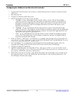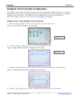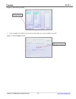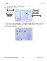
IM
1133-C
DIII-NET COMMUNICATION GATEWAY
9
www.DaikinApplied.com
5.
Install 120/24 VAC transformer in the control cabinet.
The DIII-NET Communication Gateway must have its own,
power supply.
6.
Wire 120VAC power to the transformer using open terminals from the T1 transformer inside the unit control cabinet.
The secondary of this transformer must remain ungrounded.
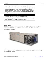
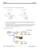
Figure 4, DIII-NET Communication Gateway mounted in unit
7.
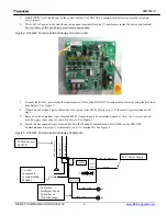
Connect the 24VAC power from the transformer to X6A on the DIII-NET Communication Gateway using the provided
wire harness. See Figure 5.
8.
If there are fewer than 2 pairs of modbus wires going to the MCB, skip to step 11. If there are 2 pairs continue with
step 9.
9.
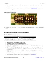
Remove 1 pair of modbus wires from the MCB. (A positive and its associated negative.)
Note: the 2 wires removed
must be a pair connecting the same two devices.
See Figure 6.
10. Attach the disconnected wires from the MCB to the Modbus Communication Port (X2M) on the DIII-NET
Communication Gateway. (+ to terminal A, and – to terminal B.) See Figure 5.
Figure 5, DIII-NET Communication Gateway Schematics
B-
A+
X7-1 X7-2
DKND3
X6A -1
X6A -2
X6A -3
BLK 2
60A
-2 B
-/
1
WHT
260
A-3
A
+/
1
DRN
26
0A-
4
COM/
1
251A-1I D3.24V/2.51
263A-4I
1 2 3 4
1 2 3 4
DS1
DS2
ON
OFF
267A-1 TB2
268A-1 TB2
128
129
24 V Power Supply
To Modbus port
on MCB
To other
components
communicating
Modbus
To Daikin
Intelligent Touch
Controller or
iTouch Manager


