Installation Manual
ED72-975
40
BRC1E61
3P243521-1
6
English
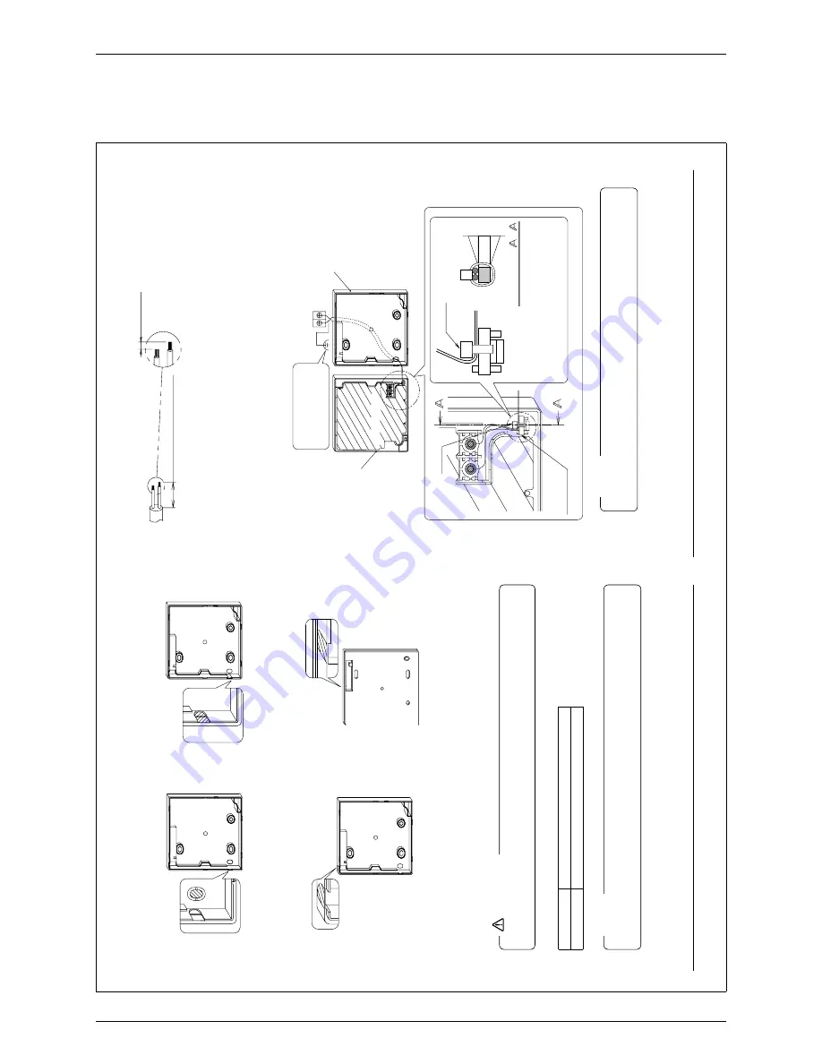
Sheath part in the remote controller case should be stripped.
Peel the shield and sheath
Cutting guideline
of the wiring
Ca. 10mm
For easy wiring, it is better to
keep ca. 10mm dif
ference
between the length of two wires.
Sheath stripping length:
Ca. 150mm for upper outlet
Ɣ
Ca. 200mm for upper center outlet
Ɣ
Connect the terminals (P/P1, N/P2) of the remote controller upper case with the terminals (P1, P2)
of the indoor unit. (P1 and P2 have no polarities.)
Back outlet
3-5-1
<W
iring fixing guideline>
Lower case
P1
Indoor unit
P2
Upper case
PC-board
Clamp
Wiring fixing
point
Cross-section
-
Secure the wiring at
the wiring fixing point
by using attached
clamping material.
Clamp
Ground the shielded
part on the indoor
unit side. (NOTE.1)
1)
Shield wire (2 wire) can be used for remote controller wiring, but it must
confi
rm to EMC (Electromagnetic Compatibility) (Australian regulation)
NOTE
.
01_EN_3P243521-1.indd 6
2/3/2009 1:19:17 PM
English
5
Determine the direction of controller wiring outlet (back
3-4
outlet, left outlet, upper center outlet, upper outlet).
Back outlet
3-4-1 Left
outlet
3-4-2
Cut of
f resin area (hatched area).
Cut of
f thin area (hatched area)
with nippers
or the like, and then
remove burr with a fi
le or
the like.
Upper outlet
3-4-3
Upper center outlet
3-4-4
Cut of
f thin area (hatched area)
with nippers
or the like, and then
remove burr with a fi
le or
the like.
Cut of
f thin area (hatched area)
with nippers
or the like, and then
remove burr with a fi
le or
the like.
Conduct wiring.
3-5
1.
Switch box and transmission wiring are not attached.
Do not directly touch the remote controller PC-board.
2.
CAUTION
Wiring Specifi
cations
Wiring
T
ype
Sheathed vinyl cord or cable (2 wire) (NOTE)
Wiring Size
0.75-1.25mm²
Shield wire (2 wire) can be used for remote controller wiring, but it must confi
rm to EMC
(Electromagnetic Compatibility) (Australian regulation)
NOTE
01_EN_3P243521-1.indd 5
2/3/2009 1:19:16 PM


