


3.7 Configuring the Welbee Inverter series welding power source
3-21
3.7 Configuring the Welbee Inverter series welding power
source
This section describes the front panel operations and internal functions of the welding power source when a
Welbee Inverter series welding power source is to be connected with the robot.
3.7.1 The welding power source operations when a robot is connected
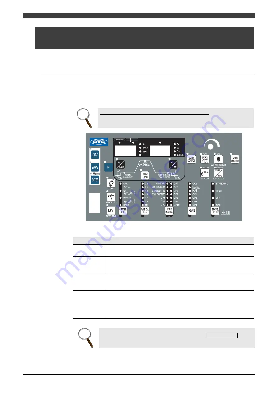
When Welbee Inverter Series welding characteristics is connected to the robot, operable keys are
displayed in Table 3.7.1. The keys, other than the ones indicated, cannot be used.
All basic settings such as selecting the welding modes and setting the welding conditions are
performed by commands from the robots.
INFO.
Concerning the operation of the welding power source
For details on how to operate the welding power source, refer to its instruction
manual.
Figure 3.7.1 Welbee Inverter series welding power source Front Panel
Table 3.7.1
Keys that can be used when the welding power source is connected to a robot
Key name
Description of function
LOAD
Used when saving a simple data log to a USB memory. For details, see the
instruction manual for the welding power source.
ENTER
This key cannot work alone. Press [ENTER] key for a while (Approx. 3 sec.) to
switch the key lock ON/OFF.
When the key lock is ON, LED for [ENTER] key flashes.
GAS CHECK
When the key is pressed once, gas is discharged (for up to 2 minutes), and
the LED lights. When it is pressed again, the gas discharge stops, and the
LED goes off.
F
When the key lock is disabled, the functions (status settings) become
available by holding down this key for a few seconds. But the settings of the
functions are ignored when Welbee Inverter series is configured for a robot.
If holding down the [F] key when turning ON the power, the software version is
displayed.
INFO.
When set for the robot dedicated application, all LEDs in TRAVEL SPEED key are
OFF.
Summary of Contents for OTC Almega AX Series
Page 10: ......
Page 69: ...1 4 Welding mode lists 1 59...


