Detect line
Draw border line to trigger snapshot which is similar to actual coil. When
vehicle reach this line, snapshot will be triggered.
Detect line is available inside drawn region only.
Select and click on redraw to drawn region as red box in Figure 4-8.
Front/Rear
When you select front, lane arrow is downward. When you select rear, lane
arrow is upward. These are vehicle moving direction with different
representations.
Car Region
Used to detect vehicle flow region.
C Area
Used to verify calibrated area.
C Check
Used to verify accuracy of calibration result.
Click “C Check”, draw line in the area and it shows actual length.
Click “Redraw” to delete original line.
Chart 6-13
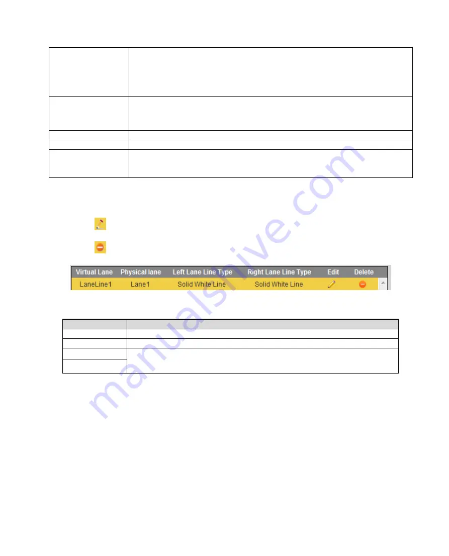
Step 4. After lane line is drawn, it auto shows lane info.
Click
corresponding lane to set.
Click
to delete current lane line. Click Yes you are done.
Figure 6-31
Parameter
Note
Virtual Lane
Set drawn virtual lane name.
Physical Lane
According to actual condition, set lane no.
Left Lane Line
Set lane line type, you can select white solid lane, white void line and
yellow lien.
Right Lane Line
Chart 6-14
Step 5. Click OK to set.
6.5.1.3.2 Video Analysis-Light Group
By setting camera installation position, you can measure video speed.
Select Setting>ITC>Intelligent>Video Analysis>Speed Measuring. After setup is complete, click OK.
See
and
Warning:
Setup value must match actual value, otherwise video speed measurement will be inaccurate.
Summary of Contents for ITC231-RF1A-IR
Page 13: ...Chart 2 1 2 2 Side Panel Figure 2 2 2 3 Front Panel Figure 2 3 ...
Page 18: ...4 System Network Please refer to Figure 4 1 Figure 4 1 Figure 4 2 ...
Page 19: ......
Page 81: ...Figure 6 64 Step 3 Click Next see Figure 6 65 Figure 6 65 ...
Page 84: ...Figure 6 68 2 Click Install Certificate See Figure 6 69 ...
Page 85: ...Figure 6 69 3 Click Next see Figure 6 70 Figure 6 70 ...


