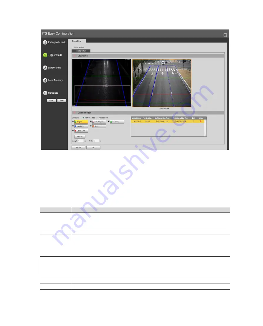
Figure 6-15
Step 1. Select config line you want to draw.
Step 2. Draw line within visible range.
Note:
Click Redraw to delete current config line.
In lane direction select head or rear to quickly switch lane direction.
Parameter
Note
Direction
Both indicator direction of vehicle, but algorithms are different.
Select head, lane arrow is down.
Select rear, lane arrow is up.
Region
Set area to be detected. Area is shown in green box.
Lane Line
According to actual traffic condition, draw lane to be detected.
Each lane needs two lines.
Lane arrow means direction of vehicle.
Lane line is shown in blue with arrow.
Detect Line
Draw intelligent border line for snapshot which is used as loop in actual
traffic. When a vehicle reaches this line, it will snapshot.
Delete line is only effective within drawn lane, not outside the area.
Delete line is red.
Car Region
Used to detect vehicle flow region.
C Area
Used to verify calibrated area.
Summary of Contents for ITC231-RF1A-IR
Page 13: ...Chart 2 1 2 2 Side Panel Figure 2 2 2 3 Front Panel Figure 2 3 ...
Page 18: ...4 System Network Please refer to Figure 4 1 Figure 4 1 Figure 4 2 ...
Page 19: ......
Page 81: ...Figure 6 64 Step 3 Click Next see Figure 6 65 Figure 6 65 ...
Page 84: ...Figure 6 68 2 Click Install Certificate See Figure 6 69 ...
Page 85: ...Figure 6 69 3 Click Next see Figure 6 70 Figure 6 70 ...


