EE Pro for TI - 89, 92 Plus
Analysis - Two-Port Networks
34
Chapter 9
Two-Port Networks
This chapter covers the basic properties of two-port network analysis under three topical headings.
Parameter Conversion
Circuit Performance
Interconnected Two-Ports
9.1 Parameter Conversion
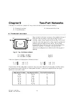
Many electrical or electronic systems are often modeled as two-port
networks with four variables, namely input voltage V1, input
current I1, output voltage V2, and output current I2. The two-port
network is a black-box approach to solving simple to sophisticated
problems of electrical and electronic circuits. The schematic
representation (Fig. 9.1) shows a two-port network where all four
variables are identified. For instance, a two-port network
characterized by
z
parameters is defined by the following pair of
equations:
Fig. 9.1 Two- Port Network Model
V
I
Z
I
Z
1
1
11
2
12
= ⋅
+
⋅
Eq. 9.1.1
V
I
Z
I
Z
2
1
21
2
22
= ⋅
+
⋅
Eq. 9.1.2
The four components of
z
parameters are defined as follows:
Z
V I
11
1
1
=
with I
0
2
=
Z
V I
12
1
2
=
with I
0
1
=
Z
V I
21
2
1
=
with I
0
2
=
Z
V I
22
2
2
=
with I
0
1
=
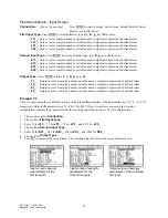
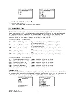
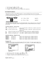
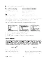
The table below lists the independent variables for two-port circuits, followed by the dependent variables and two-
port parameters associated with each set of independent variables. Conversion of parameters from one type to
another is covered in this section.
Independent Variables
Dependent Variables
Two-Port Parameter Type
I1, I2
V1, V2
z
V1, V2
I1, I2
y
I1, V2
V1, I2
h
I2, V1
I1, V2
g
V2, I2
V1,
-
I1
b
V1, I1
V2,
-
I2
a
z, y, h, g,
a or b
V
2
V
1
I
2
I
1
input
output
V
2

