EE Pro for TI-89.92 Plus
Analysis - Ladder Networks
22
5.2 Using the Ladder Network
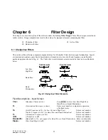
General instructions for entering the elements and computing the parameters of a ladder network.
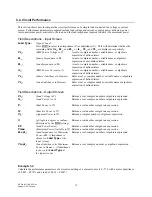
1. The initial screen prompts the user for entry of values for
Frequency
and
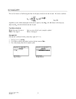
Load
.
2. Build the ladder by adding elements to it. Press
‰
to insert the first element. Choose an element type and
press
¸
. Enter the appropriate values. Press
„
to update the ladder with the new element just added. A
second press of the
„
key computes the electrical performance of the circuit.
3. New elements can be added or inserted by moving the highlight bar to the location desired and pressing
‰
.
The new element will appear after the a highlighted element.
4. A circuit element can be deleted from the ladder by moving the highlight bar to the element and pressing
Š
.
..
5. Press
„
to compute the overall ladder network parameters.
6. Previously calculated results are not automatically updated for new element entries; the user must press
„
to
re-solve for the circuit parameters for a new circuit configuration.
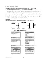
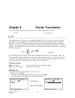
Example 5.1
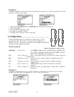
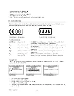
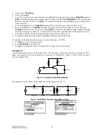
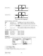
What is the input impedance of the circuit shown below in Fig. 5.1 at 1 MHz and 10 MHz?
50
Ω
50
Ω
100 pF
10E-6 H
50 pF
Load
Element 1
Element 2
Element 3
Element 4
Fig. 5.1 Ladder Network Example
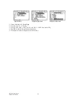
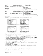
Entering Load and Frequency
Partial list of Element Choices
Typical Edit Screen for an Element
List of all the Ladder Components
Output Screen at 1 MHz
Output Screen at 10 MHz
.


