4 Configuration
D-Link Web Smart Switch User Manual
26
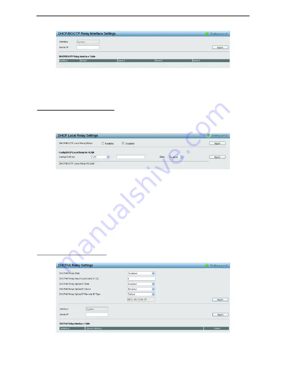
Figure 4.27 – System > DHCP/BOOTP Relay > DHCP/BOOTP Relay Interface Settings
Interface
: The IP interface on the Switch that will be connected directly to the Server.
Server
IP: Enter the IP address of the DHCP/BOOTP server. Up to four server IPs can be configured per IP
Interface.
Click
Apply
to implement changes made.
System > DHCP Local Relay Settings
The DHCP Local Relay Settings page allows the user to configure DHCP Local Relay. DHCP broadcasts are
trapped by the switch CPU, and replacement broadcasts are forwarded with Option 82. Replies from the
DHCP servers are trapped by the switch CPU, the Option 82 is removed and the reply is sent to the DHCP
Client.
Figure 4.28 - System > DHCP Local Relay Settings
DHCP/BOOTP Local Relay Status:
Specifies whether DHCP Local Relay is enabled on the device.
Enabled –
Enables DHCP Local Relay on the device.
Disabled –
Disables DHCP Local Relay on the device. This is the default value.
Config VLAN by:
Configure the VLAN by VID or VLAN Name of drop-down menu.
State:
Specifies whether DHCP Local Relay is enabled on the VLAN.
Enabled –
Enables DHCP Local Relay on the VLAN.
Disabled –
Disables DHCP Local Relay on the VLAN.
DHCP Local Relay VID List:
Displays the list of VLANs on which DHCP Local Relay has been defined.
Click
Apply
to implement changes made.
System > DHCPv6 Relay Settings
The DHCPv6 Relay Settings page allows user to configure the DHCPv6 settings.
Figure 4.29 - System > DHCPv6 Relay Settings


