background image

DES-7000/DES-7100 Layer 2 Switch User

s Guide


Using the Web-based Management Software  

50


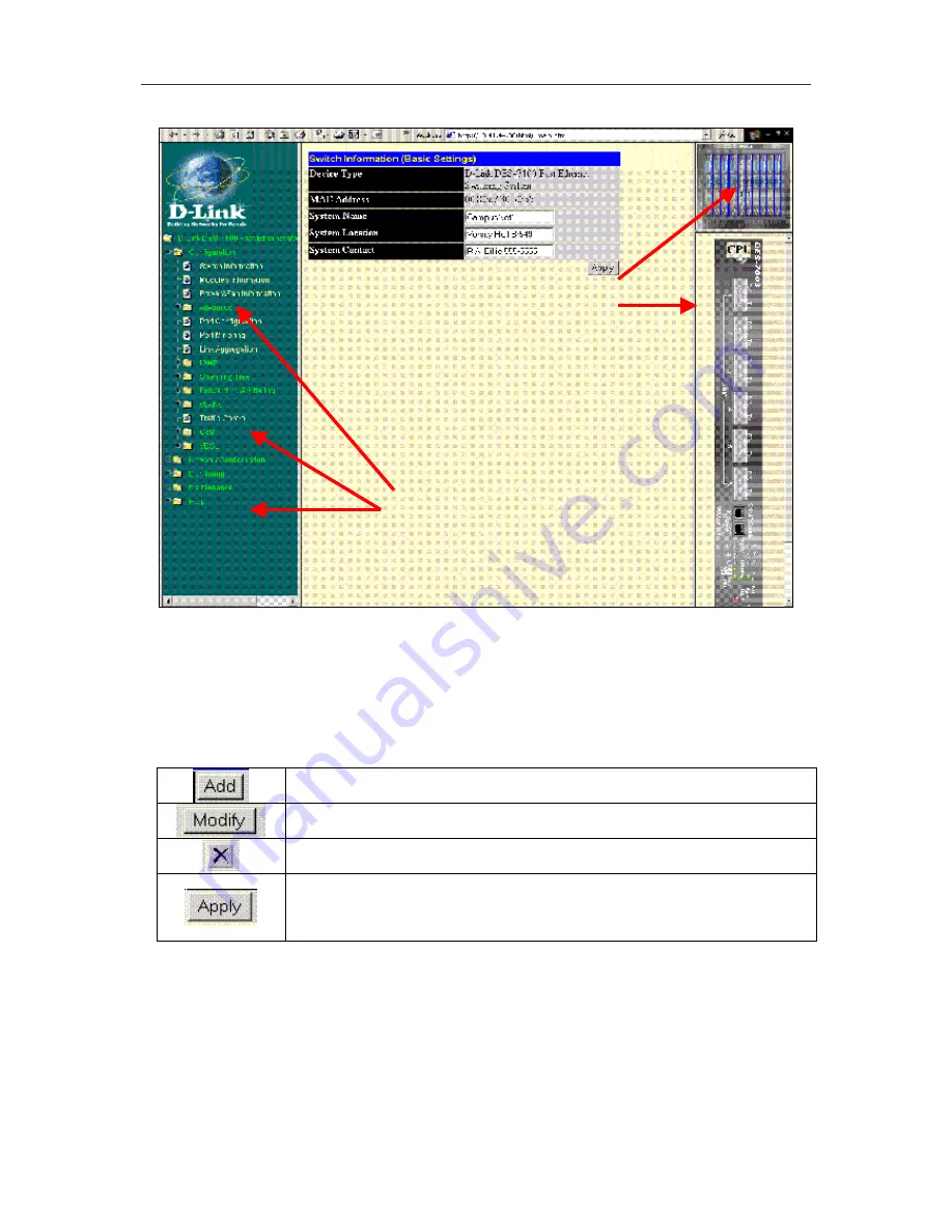
Figure 6- 2. Web Manager Folders and Menus 

The  various  menus  available  for  use  in  the  web  manager  are  organized  into  four  general  categories 
contained  in  separate  folders.  The  categories  (folders)  are 

Configuration

Network  Configuration

Monitoring

 and 

Maintenance

. This chapter is organized in the same fashion as the menus in the web 

manager and presented in the same order.  

Commonly Used Buttons 

The following buttons are used throughout the web management application on the various menus. 


Used to create a new set of parameters for the function or application. For most 
menus this will bring up a new menu used for configuration. 


Used to change an exiting set of parameters. The menu used to changes 
configuration settings are very similar to the menus used for creating a new set. 


Clicking this will delete the previously created configuration set, such as a 
VLAN or port trunk group.  


Clicking this will apply the settings as they appear in the menu. This does not 
save the settings however. Configuration settings must be saved using the 
save function or they will be lost if the system or relevant switch module is 
rebooted or powered off.   

CLI Reference vs. Web Manager 

The  web-based  management  menus  presented  here  are  organized  somewhat  differently  than  in  the 
CLI  Reference  Manual.  The  material  in  this  chapter  follows  roughly  the  same  order  that  the  menu 
hyperlinks  appear  in  the  left  side  panel  of  the  web  interface.  For  the  purpose  of  cross  referencing, 
many  of  the  sections  describing  web  manager  menus  also  list  the  corresponding  CLI  command  or 
commands  in  their  basic  form.  The  CLI  cross-references  do  not  contain  the  entire  syntax  for  the 
command.  Please  read  the  CLI  Reference  Manual  to  view  the  entire  syntax  for  the  CLI  commands. 
Since  some  command  groups  are  very  large,  only  the  section  of  the  CLI  Reference  Manual  that  is 
relevant to the material discussed is referenced instead of listing all the relevant commands.  

Click  on  any  folder  to  reveal  the 
subfolders  or  hyperlinked  menu 
buttons inside. 

Click  on  a  module  to  see  a 
virtual  panel  display  for  that 
module in near real time 

Summary of Contents for DES-7000 Series

Page 1: ...DES 7000 DES 7100 Layer 2 Modular Chassis based Switch User s Manual First Edition February 2003 6DES7000 01 Printed In Taiwan RECYCLABLE ...

Page 2: ...aum nicht benutzt sollten Sie es vom Stromnetz trennen Somit wird im Falle einer Ü berspannung eine Beschä digung vermieden 13 Durch die Lüftungsö ffnungen dürfen niemals Gegenstä nde oder Flüssigkeiten in das Gerä t gelangen Dies kö nnte einen Brand bzw Elektrischen Schlag auslö sen 14 Ö ffnen Sie niemals das Gerä t Das Gerä t darf aus Gründen der elektrischen Sicherheit nur von authorisiertem Se...

Page 3: ...rranty period D Link will provide repair or replacement of the product D Link shall have the sole discretion whether to repair or replace and replacement product may be new or reconditioned Replacement product shall be of equivalent or better specifications relative to the defective product but need not be identical Any product or part repaired by D Link pursuant to this warranty shall have a warr...

Page 4: ... that all defects in the software product within or without the scope of D Link s applicable product documentation will be corrected D Link Offices for Registration and Warranty Service The product s Registration Card provided at the back of this manual must be sent to a D Link office To obtain an RMA number for warranty service as to a hardware product or to obtain warranty service as to a softwa...

Page 5: ... 20 Rear Panel Views 21 Ports 23 LED Indicators 24 AC Power Redundant Power Supplies 26 Push Buttons 26 Fans 26 Network Cabling and Connections 28 Connect to the DES 7003 CPU Management Uplink Module 28 Connect to the DES 7005 10BASE T 100BASE TX Module 28 Connect to the DES 7006 100BASE FX Module 28 Connect to the DES 7010 Ethernet over VDSL Module 29 Cable Lengths 29 Switch Management 30 Local C...

Page 6: ... 65 Static Multicast Forwarding 66 Static MAC Address Filtering 66 VLANs 67 Configure 802 1Q Static VLANs 67 802 1Q Port Settings 70 Defined Router 71 Traffic Control Broadcast Multicast Storm Control 72 Quality of Service QoS 73 Port Priority 73 VDSL Configuration and Monitoring 75 VDSL Port Rate Adaptive 75 View VDSL Transmission Power and SNR 76 VDSL Loopback Test 77 Network Configuration 78 IP...

Page 7: ...Configuration File 96 Save Settings 97 Save History Log 97 Switch History 98 Ping Test 99 Save Changes 99 Factory Reset 100 Restart System 100 Technical Specifications 101 Index 103 ...

Page 8: ...ink modules Duplicate CPU modules support redundant backup function Twelve slots to install DES 7000 Series switch modules DES 7100 Switch Chassis Eight slots for installing networking modules Two slots reserved for the preinstalled management CPU Uplink modules Duplicate CPU modules support redundant backup function Six slots to install DES 7000 Series slave modules DES 7003 Management Uplink CPU...

Page 9: ...upports 16 MB packet buffer memory per module Supports 8K MAC address per Switch blade Two LED indicators for each port for Link Activity and Speed DES 7006 24 Port 100BASE FX SFF type SMF MMF Ethernet Switch Module The DES 7006 includes 24 Fast Ethernet ports SFF type LC Duplex Fully compliant with IEEE 802 3u standard IEEE 802 3x compliant Flow Control supported for Full duplex Supports 16MB pac...

Page 10: ...n information below Current sharing load balancing design Full redundant feature design to ensure continuous operation Hot swappable Power management functions enabled Use this table to calculate total power consumption for the Switch chassis Do not exceed the 730 Watt maximum for each RPS unit For best load balancing performance and RPS lifespan it is recommended to allow for redundancy Two RPS u...

Page 11: ... shipped components 1 One switch chassis including One pre installed DES 7003 CPU uplink module One pre installed DES 7011 power supply unit For DES 7000 chassis only one pre installed fan tray module with four fans 2 One cable bearer DES 7000 only 3 Four wheels DES 7000 only 4 One AC power cord 5 One RJ 45 to RS 232 9 pin male serial adapter 6 One CD ROM containing documentation for the device 7 ...

Page 12: ...alled and powered on Modules can be hot swapped to meet the changing demands of the network Attaching Wheels The DES 7000 is shipped with four wheels that may be install but are not required To install the wheels gently place the chassis on either of its sides to access the wheel mounts Make sure the fan module is firmly in place before tilting the chassis Each wheel is held in place with four scr...

Page 13: ...need to install them Follow the instructions below Modules can be installed into any free slot except the CPU module WARNING When handling Switch modules be sure to wear an ESD wrist strap or suitable grounding device to prevent damage from electrostatic discharge Do not attach the strap to any part of the power supply if the Switch is powered on Figure 2 3 Inserting a module into the DES 7000 Fig...

Page 14: ...ndicators are on the bottom Modules installed in the DES 7100 should be inserted horizontally in the upright position that is so the model number and LED indicator labels are displayed so they can be read from left to right 4 Push the ejector levers toward the center of the module until they touch the front of the module This will push the bus connectors into backplane of the chassis 5 Hand tighte...

Page 15: ...ollows All indicators will flash momentarily indicating a system reset The Power indicator will flash for a few seconds during the POST The System Status LED indicator will be dark during CPU arbitration for several seconds The System Status and Power LED indicators will light steady green indicating normal system and power supply function An amber light in either of these indicates a problem Powe...

Page 16: ...er suitable instrument 2 Observe the Hot Swap Card Status LED indicator on the switch module being removed It should blink amber During this phase the module is sending a message to the master CPU module that a removal has been initiated 3 The master module detects the removal and updates its database The master module cuts power to the switch module being removed The Power LED indicator and all o...

Page 17: ...ted so the model number of the module is at the top and the LED indicators are on the bottom 4 Push the ejector levers toward the center of the module until they touch the front of the module This will push the bus connectors into backplane of the chassis 5 Observe the Hot Swap Card Status LED indicator on the switch module This will blink amber for about 13 seconds after being inserted During thi...

Page 18: ...plying upward pressure on the catch release near the left side of the unit 3 Pull the RPS unit straight out from the chassis Inserting a DES 7011 RPS Module into the DES 7000 chassis To insert an RPS module push the unit straight in toward the back of the chassis until the catch snaps into place securely holding the RPS in position Pull up to release RPS module RPS status LED indicators ...

Page 19: ...t is cut off Use only the handle on the front of the fan tray when removing the device to avoid risk of injury Inserting the fan tray into the DES 7100 chassis To change the fan tray 1 Unscrew the installation screws on each side of the module and pull the module from out of the chassis Be careful not to drop the fan tray when removing it 2 Replace the fan tray module immediately if the Switch is ...

Page 20: ...cators ports and power supply Front Panel Views Figure 3 1 Front panel view of DES 7100 with DES 7010 Ethernet over VDSL Modules The front panel of the DES 7100 features one installed redundant power supply The remaining two slots are available for additional RPS units RPS slots are located along the top of the device and are labeled L left M middle and R right Network module slots are labeled wit...

Page 21: ...el of the DES 7000 features one installed redundant power supply The remaining slots are available for additional RPS units RPS slots are located along the bottom of the device and are labeled L left M middle and R right Network module slots are labeled with the name of the slot along the top of the fan tray The master CPU module is installed in the center slot labeled CPU A ...

Page 22: ...tem fans are used to dissipate heat Do not block these openings and leave adequate space at the rear and sides of the Switch for proper ventilation Without proper heat dissipation and air circulation system components might overheat which could lead to system failure Figure 3 1 Right and Left Side Panel Views of the DES 7000 Figure 3 2 Right and Left Side Panel View of the DES 7100 ...

Page 23: ...sed with battery back up systems These systems should be installed by a qualified technician Please contact your vendor for information about battery back up systems The RS 232 console port on the lower right side of the rear panel is used with DES 7012 RPS units only The console port is not used with DES 7011 RPS units Figure 2 6 Rear panel of DES 7000 WARNING Do not remove the panels covering th...

Page 24: ... the back of the Switch Please read and observe the cautionary statement regarding removal of the back panel The battery connection terminals are used with battery back up systems These systems should be installed by a qualified technician Please contact your vendor for information about battery back up systems The RS 232 console port is used with DES 7012 RPS units only The console port is not us...

Page 25: ...f band management and system configuration requires adapter included with Switch 6 GBIC Gigabit Ethernet Ports for Uplinking Switch to network backbone LED Indicators for monitoring status system alerts and hot swapping DES 7005 Ethernet Fast Ethernet Module 24 10BASE T 100BASE TX RJ 45 Ports All ports support auto polarity detection MDI X MDI II Connects to 10BASE T and 100BASE TX devices at full...

Page 26: ...tes abnormal function Abnormal function can include RPS failure fan failure or temperature problem Any of these problems will also trigger an audible alarm the system buzzer Utilization Eight scales are used 1 5 10 20 30 50 70 90 to indicate traffic rate to the CPU Hot Swap Card Status This will begin to blink amber when a hot swap of the unit has been initiated It should begin blinking immediatel...

Page 27: ...tage problem with this module Hot Swap Card Status This will begin to blink amber when a hot swap of the unit has been initiated It should begin blinking immediately after the Hot Swap button has been pushed After a few seconds the module will be powered off and it may be safely removed Per Port Indicators Switch modules include per port LED indicators that differ for each module The DES 7005 has ...

Page 28: ... them with a ballpoint pen or other suitable instrument The functions activated by the buttons are described as follows System Buzzer DES 7003 CPU modules only A warning sounds when any system fans fail or when the fan tray unit has been removed Depressing the System Buzzer button will silence the fan fail alarm Hot Swap This is used to initiate a hot swap of the module See the section on hot swap...

Page 29: ...red down The shutdown sequence is as follows If two fans fail all slave modules and the backup Master will be powered off after 30 minutes if not replaced If three fans fail all slave modules and the backup Master will be powered off after 10 minutes If four fans fail all slave modules and the backup Master will be powered off after 5 minutes ...

Page 30: ...tly to a computer with standard Ethernet cable to the Ethernet port on a computer Connect to the DES 7005 10BASE T 100BASE TX Module Network connections to the 24 ports of the Ethernet module are made using Category 5 or better cabling with RJ 45 UTP connectors Ports may be connected to network devices that support 10BAES T or 100BASE TX operation All ports support auto negotiation by default for ...

Page 31: ...e remote CPE unit per port to the module The switch module to end users connection can be done through a variety means depending on the circumstances including using a Main Distribution Frame Cabling Cabinet patch panels or other suitable wiring systems This provides the combined data and voice channels to the VDSL accounts The per port LED Link indicators on the DES 7010 will Light green when a l...

Page 32: ...y for configuration data operational programs and SNMP agent firmware These components allow the switch to be actively managed and monitored from either the console port or the network itself out of band or in band Use the console connection to setup user accounts and assign IP settings When these tasks have been completed the Switch can be connected to the network and configured as desired There ...

Page 33: ...nnected to the network User accounts not configured at the factory and there is no default user account The first time the Switch is set up or following a reset all command you may simply press the Enter key when prompted for a user name and again for the password prompt The command prompt DES 7000 4 will now appear You may proceed to enter CLI commands If a portion of a command is not recognized ...

Page 34: ...min user name Then you are be prompted for a new password type the case sensitive password and press Enter Type the same password again to confirm it Figure 5 2 Create Administrators User Account The Success message indicates the new user account has been successfully created If the new password entry does not match the confirmation you will be prompted to repeat the password entry Be sure to save...

Page 35: ...management software or Telnet is enabled by default Once you have the IP settings of the Switch configured you can use either of these methods to manage the Switch In band management can be done remotely through the network using Telnet the web based management You may also use a Telnet or web interface for out of band management by connecting directly to the Switch s dedicated Management port lab...

Page 36: ...rding tables see page 65 MAC Address Aging Time The Aging Time affects the learning process of the Switch Dynamic forwarding table entries are made up of the source and destination MAC addresses and their associated port numbers and are deleted from the table if they are not accessed within the aging time The aging time can be adjusted from 10 to 2200 seconds with a default value of 300 seconds A ...

Page 37: ...mplicated and complex subject and must be fully researched and understood It is possible to cause serious degradation of the performance of the network if the Spanning Tree is incorrectly configured Please carefully read understand this section before making any changes from the default values The Switch allows two levels of spanning trees to be configured The first level constructs a spanning tre...

Page 38: ...ure the VLAN or port STP parameters listed here Variable Description Default Value Port Priority A relative priority for each port lower numbers give a higher priority and a greater chance of a given port being elected as the root port 32768 Port Cost A value used by STP to evaluate paths STP calculates path costs and selects the path with the minimum cost as the active path 10 Bridge Protocol Dat...

Page 39: ...nabled using the default parameters the path between source and destination stations in a switched network might not be ideal For instance connecting higher speed links to a port that has a higher number than the current root port can cause a root port change The goal is to make the fastest link the root port STP Port States The BPDUs take some time to pass through a network This propagation delay...

Page 40: ...individual ports please read Port Configuration on page 55 for a description of how the DES 7000 DES 7100 implements learning on the Switch If it is disabled for the port this port state is skipped A port transitions from one state to another as follows From initialization switch boot to blocking From blocking to listening or to disabled From listening to learning or to disabled From learning to f...

Page 41: ...ets also called Hello messages are no longer forwarded Observe the following formulas when setting the above parameters Max Age 2 x Forward Delay 1 second Max Age 2 x Hello Time 1 second Port Priority A Port Priority can be from 0 to 255 The lower the number the greater the probability the port will be chosen as the Root Port Port Cost A Port Cost can be set from 1 to 65535 The lower the number th...

Page 42: ...k using STP The switch with the lowest Bridge ID switch C was elected the root bridge and the ports were selected to give a high port cost between switches B and C Note also that the example network topology is intended to provide redundancy to protect the network against a link or port failure not a switch failure or removal For example a failure of switch A would isolate LAN 1 from connecting to...

Page 43: ... VLAN can freely exchange packets through the VDSL Switch Once the VLAN has been created there should not be any more configurations decisions for the VDSL Switch manager as long as there are no additional ports required by the client If the client prefers to lease additional bandwidth i e more ports these can be easily added to the client s VLAN if there are unused ports available on the Switch T...

Page 44: ...les determines if the packet must be sent tagged or untagged Packet Forwarding in 802 1Q VLANs The diagram below illustrates packet forwarding decisions with 802 1Q VLANs Figure 5 7 Packet Forwarding with VLANs 802 1Q VLAN Tags The figure below shows the 802 1Q VLAN tag There are four additional octets inserted after the source MAC address Their presence is indicated by a value of 0x8100 in the Et...

Page 45: ...e 5 9 Adding 802 1Q Tag to a Packet Header Port VLAN ID Packets that are tagged are carrying the 802 1Q VID information can be transmitted from one 802 1Q compliant network device to another with the VLAN information intact This allows 802 1Q VLANs to span network devices and indeed the entire network if all network devices are 802 1Q compliant Unfortunately not all network devices are 802 1Q comp...

Page 46: ...the VID number priority and other VLAN information into the header of all packets that flow into and out of it If a packet has previously been tagged the port will not alter the packet thus keeping the VLAN information intact The VLAN information in the tag can then be used by other 802 1Q compliant devices on the network to make packet forwarding decisions Ports with untagging enabled will strip ...

Page 47: ...torms Eliminating Broadcast Storms SNMP agents can be programmed to monitor the number of broadcast packets on switch ports and act on the data When the number of broadcast packets on a given port rises past an assigned threshold an action can be triggered When enabled the rate of broadcast packets coming in through the affected port will be limited Any traffic above the threshold limit will be di...

Page 48: ...n of a portion of the multicast IP address within the reserved range and the MAC address of the recipient Multicast groups can be administered manually using the Static Multicast Forwarding table see page 66 IGMP Internet Group Management Protocol IGMP is a Layer 3 protocol used by multicast recipient hosts to communicate multicast group membership information to local or nearest routers Receiving...

Page 49: ...l Specifies the maximum amount of time between group specific query messages including those sent in response to leave group messages Default 1 Host Timeout This is the maximum amount of time in seconds allowed for a host to continue membership in a multicast group without the Switch receiving a host membership report Default 260 Route Timeout This is the maximum amount of time in seconds a route ...

Page 50: ...network the workstation used should be on the same subnet as the Switch You may also use Telnet or the web based software if the Switch is connected directly to a computer via the Mgmt port on the front of the Primary Master CPU module The Mgmt port is a dedicated Ethernet port used for out of band access to the management software User accounts user name and password for the Switch should be set ...

Page 51: ...nd double click on the corresponding menu button As illustrated in the example below the web based management GUI presents a virtual representation of the entire Switch in the upper right portion of the browser window The lower right portion displays the primary CPU management module initially This view can be changed to display any of the installed functioning modules on the Switch chassis To vie...

Page 52: ...l apply the settings as they appear in the menu This does not save the settings however Configuration settings must be saved using the save function or they will be lost if the system or relevant switch module is rebooted or powered off CLI Reference vs Web Manager The web based management menus presented here are organized somewhat differently than in the CLI Reference Manual The material in this...

Page 53: ...menu The System Information displays general information about the Switch including its MAC Address You can also enter a System Name System Location and the name and telephone number of the administrator in the System Contact It is recommended that the person responsible for the maintenance of the network system be listed here Click on the Apply button to make the changes effective To view this in...

Page 54: ...e 6 4 Modules Information Information about the installed modules includes the type of module the boot PROM version the firmware version number and the hardware revision designation The modules are listed according to the slot name Slots L7 and L8 are reserved for the primary CPU management module and the optional redundant management module Advanced Settings Figure 6 5 Switch Information Advanced...

Page 55: ...ooping switch wide using Telnet use CLI command enable igmp_snooping To enable system wide IGMP Snooping capability select Enabled IGMP snooping is Disabled by default Enabling IGMP snooping allows you to specify use of a multicast router only see below To configure IGMP Snooping for individual VLANs use the IGMP Snooping Settings menu see page 60 Multicast Router Only To enable Telnet use CLI com...

Page 56: ...o provide only DHCP or BOOTP service Connecting a DCHP or BOOTP enabled router or Layer 3 switch to the Management Port will allow ordinary network traffic through the port If this is unavoidable consider assigning the IP settings manually and configure the network DHCP or BOOTP server to account for the manual assignment The CLI command config mgmt_port is used for management port configuration F...

Page 57: ...configuration is concerned is summarized below Type DES 7003 DES 7005 DES 7006 DES 7010 Speed 10 or 100 Mbps 100 Mbps only Adjustable for upstream and downstream speed customization Duplex Uplink ports for Optical Gigabit Ethernet operate at 1000 Mbps in full duplex only Full or Half Full only N A Flow Control Enable or Disable per port Enable or Disable per port Enable or Disable per port N A Lea...

Page 58: ...r disable learning for the selected ports When Enabled destination and source MAC addresses are automatically listed in the forwarding table When learning is Disabled MAC addresses must be manually entered into the forwarding table This is sometimes done for reasons of security or efficiency See the section titled Forwarding and Filtering on page 65 for information on entering MAC addresses into t...

Page 59: ...d devices connected to that port cannot use the Switch and the Switch purges their addresses from its address table after the MAC address aging time elapses Speed Duplex GBIC ports supports two speed duplex modes 1000M Full and Auto to support auto negotiation when connected a device that also supports auto negotiation Optical Gigabit Ethernet operates at 1000 Mbps in full duplex only Flow Control...

Page 60: ...rt you are copying frames from should always support an equal or lower speed than the port to which you are sending the copies Also the target port for the mirroring cannot be a member of a trunk group Please note a target port and a source port cannot be the same port Link Aggregation Link Aggregation allows multiple ports to be grouped together and to act as a single link This gives a bandwidth ...

Page 61: ...te a port trunk group click the Modify or Delete option in the Current Trunk Group Entries Table Figure 6 11 Port Trunking Configuration Add Menu The user changeable parameters in the Switch are as follows Select Slot Number Choose the slot on which you wish to set up a trunk group Trunk groups must be confined to ports on a single module Select Group ID Select an ID number for the group Group Nam...

Page 62: ...ific Multicast group member based on IGMP messages sent from the device to the IGMP host or vice versa The Switch monitors IGMP messages and discontinues multicasts when there are no longer hosts requesting that they continue Use the IGMP Snooping Group Entry Table to view IGMP Snooping status To modify settings click the Modify button for the VLAN ID you want to change Figure 6 12 IGMP Snooping E...

Page 63: ...terval sec Specifies the maximum amount of time between group specific query messages including those sent in response to leave group messages Default 1 Host Timeout config igmp_snooping vlan_name all host_timeout sec This is the maximum amount of time in seconds allowed for a host to continue membership in a multicast group without the Switch receiving a host membership report Default 260 Route T...

Page 64: ...er port will receive all multicast data for all VLANs The Static Router Port Entry hyperlink first presents the Static Router Ports Entry Table Figure 6 14 Static Router Ports Entry Table To designate a new static router port or to change an existing one click the Modify button for the corresponding VLAN ID number The Static Router Ports Settings menu appears Figure 6 15 Set Static Router Ports VI...

Page 65: ...witch Settings Menu Set the parameters listed below in the STP Switch Settings menu Spanning Tree Protocol Allows the STP to be globally Enabled or Disabled on the switch Default Disabled Bridge Max Age 6 40 Sec The maximum time in seconds a device can wait without receiving a configuration message before attempting to reconfigure All device ports except for designated ports should receive configu...

Page 66: ...e STP root device The lower the numeric value the higher the priority If all devices have the same priority the device with the lowest MAC address will become the root device Range 0 to 65535 Default 32 768 The relevant CLI commands for system wide STP are config stp show stp and enable disable stp Port Spanning Tree On some networks it may be desirable to disable STP for an individual port For ex...

Page 67: ... Use these menus to setup Multicast and Unicast forwarding and MAC Address filtering For relevant forwarding and filtering CLI commands please read the section titled Layer 2 FDB Commands in the CLI Reference Manual To configure the MAC address aging time used for the forwarding table see Advanced Settings page 52 for web based configuration or use the CLI command config fdb aging_time Static Unic...

Page 68: ...rt dynamically joining the multicast group None is chosen then an end station attached to the port can join the multicast group using GMRP Egress the port is a static member of the multicast group The corresponding CLI commands for the Multicast Forwarding menu are create multicast fdb config multicast_fdb and show multicast_fdb Static MAC Address Filtering Filtering based on MAC address is implem...

Page 69: ...VLAN ID VID and by name To create a new VLAN click on the New button in the header row of the table To edit an existing VLAN click on the Modify button of the VLAN you want to edit To eliminate an entire VLAN click on the X button for the VLAN you wish to delete The user configurable settings are the same when you Add or Modify a VLAN Read the next section for a description of these settings The C...

Page 70: ...being created Slot Choose the module on which you want to define VLANs A VLAN may exist on multiple modules Port Corresponds to the ports that will be members of the VLAN Tag Specifies the port as either 802 1Q tagging or 802 1Q untagging Checking the box will designate the port as Tagging None Specifies the port as not being a static member of the VLAN but with no restrictions for joining the VLA...

Page 71: ...ing VLANs are identified by name VLAN Name The name of the VLAN to be edited Slot Choose the module on which you want to define VLANs A VLAN may exist on multiple modules Port A list of the ports that are static members of the currently selected VLAN Tag Specifies the port as either 802 1Q tagging or 802 1Q untagging Checking the box will designate the port as Tagging None Specifies the port as no...

Page 72: ...to the port for transmission the port will add an 802 1Q tag using the PVID to write the VID in the tag When the packet arrives at its destination the receiving device will use the PVID to make VLAN forwarding decisions If a packet is received by the port and Ingress filtering is enabled the port will compare the VID of the incoming packet to its PVID If the two are unequal the port will drop the ...

Page 73: ...by VLAN and MAC address This form of traffic segmentation is used for security and efficiency Figure 6 25 Defined Router MAC Address Entry Table VLAN ID Enter the VID in which the router or server resides MAC Address Specify the router or server by typing its MAC address The relevant CLI information can be found in the CLI Reference manual in the section titled Traffic Segmentation The commands us...

Page 74: ...when a storm is formed because a MAC address cannot be located in the Switch s forwarding database and it must send a packet to all ports or all ports on a VLAN To configure Traffic Control select the Slot you want to configure Broadcast Storm Multicast Storm and Destination Look Up Failure may be Enabled or Disabled The Threshold value is the upper threshold at which the specified traffic control...

Page 75: ...ut causing unacceptable delays of other network traffic If QoS is not well set up however significant delays and excessive packet loss may result for data assigned to lower priority queues Port Priority This window allows you to set a default 802 1p priority to each port on the switch for packets that have not already been assigned a priority value The default priority is applied to packets transm...

Page 76: ...iguration QoS can be customized by changing the output scheduling used for the hardware queues in the Switch As with any changes to QoS implementation careful consideration should be given to how network traffic in lower priority queues are affected Changes in scheduling may result in unacceptable levels of packet loss or significant transmission delay If you choose to customize this setting it is...

Page 77: ...te cannot be maintained Figure 6 30 VDSL Port Rate Adaptive Configuration To configure Port Rate Adaptive for any VDSL module first select the Slot from the drop down menu then choose which ports are to be configured in the From and To drop down menus Choose the Rate Adaptive mode from the drop down menu Choose options Disabled Default or Optimum The setting Default will set speed to Mode 0 when a...

Page 78: ...Noise SNR ratio for VDSL ports This is sometime useful for troubleshooting and monitoring VDSL ports Power levels may be subject to local or regional regulatory restrictions Figure 6 31 VDSL Port Tx Power Table DS Tx Power Downstream Transmission Power dBm Hz US Tx Power Upstream transmission Power dBm Hz DS SNR Downstream Signal to Noise Ratio dB US SNR Upstream Signal to Noise Ration dB ...

Page 79: ...t to conduct and type in the number of repetitions for the test Click Apply to initiate the test A Local test tests connectivity from the CPU to the VDSL controller chip on the VDSL module A Line test checks connectivity to the CPE for the port s To see the results of a loopback test click the View LoopBack Test Results button The corresponding CLI command for this function is config vdsl_port_loo...

Page 80: ... or DHCP in the Get IP From menu 2 If you are assigning IP settings manually type in the IP settings for IP Address Subnet Mask and Default Gateway 3 Change the Management VLAN ID number in the Management VID box default Management VID 1 CLI command config ip vlan 4 Click Apply to let your changes take effect Important Note The GBIC uplink ports on the DES 7003 CPU module are currently not compati...

Page 81: ...fig trusted_host delete trusted_host and show trusted_hosts Note If you are not currently running the web manager from one of the IP addresses defined in the Management Station IP Settings screen you will lose access to the web manager when you click on Apply SNMP Manager Use the Community Strings menu to define up to four community strings Community strings are used to verify who can receive SNMP...

Page 82: ...g Station Type in the IP address of the trap recipient i e the IP address of the management station that will receive traps generated by the switch Community String Type in a string of up to 20 characters used for authentication of users wanting to receive traps from the switch s SNMP agent Status Choose Valid or Invalid for the string This is used to temporarily limit the receipt of traps generat...

Page 83: ... DST and the beginning of Summer Standard Time where applicable choose the week 1 1 st week of month 2 2 nd week etc day of the week and month Standard Time normally begins and DST ends Likewise define the end of Standard Time beginning of DST according to normal local practice Summer time offset is the number of hours that clocks are adjusted when the seasonal time changes occur Date and time set...

Page 84: ...and retype the same password in the Confirm New Password Choose the level of privilege Admin or User from the Access Right drop down menu To add a user account using the CLI commands use create account and config account Figure 6 41 Modify User Accounts Modify or delete an existing user account in the User Account Control Table Edit To delete the user account click on the Delete button To change t...

Page 85: ...wer and Fan Information To view this information using Telnet use CLI command show power_fan_information The Power and Fan Information table lists the current status of all system fans and power modules Figure 6 42 Power Fan Information The Power Information in the top section of the table lists the status of the power supply and redundant power supply Fan Information displays the status of the 8 ...

Page 86: ...llows Time Interval Select the desired setting between 1s and 60s where s stands for seconds The default value is one second Record Number Select number of times the Switch will be polled between 20 and 200 The default value is 20 Show Hide Check whether or not to display Utilization Clear Clicking this button clears all statistics counters on this window To view port utilization information with ...

Page 87: ...nagement Software 85 Packets The Web Manager allows various packet statistics to be viewed as either a line graph or a table The six windows offered are as follows Received RX Figure 6 44 Rx Packets Analysis window Line Chart Figure 6 45 Rx Packets Analysis window Table ...

Page 88: ...ts the number of bytes received on the port Packets Counts the number of packets received on the port Show Hide Check whether or not to display Bytes and Packets Clear Clicking this button clears all statistics counters on this window View Table Clicking this button instructs the Switch to display a table rather than a line graph View Line Chart Clicking this button instructs the Switch to display...

Page 89: ...y a unicast address Multicast Counts the total number of good packets that were received by a multicast address Broadcast Counts the total number of good packets that were received by a broadcast address Show Hide Check whether or not to display Multicast Broadcast and Unicast Packets Clear Clicking this button clears all statistics counters on this window View Table Clicking this button instructs...

Page 90: ...DES 7000 DES 7100 Layer 2 Switch User s Guide Using the Web based Management Software 88 Transmitted TX Figure 6 48 Tx Packets Analysis window Line Chart Figure 6 49 Tx Packets Analysis window Table ...

Page 91: ...lly sent on the port Show Hide Check whether or not to display Bytes and Packets Clear Clicking this button clears all statistics counters on this window View Table Clicking this button instructs the Switch to display a table rather than a line graph View Line Chart Clicking this button instructs the Switch to display a line graph rather than a table The CLI command to view packet statistics is sh...

Page 92: ...ved that were longer than 1518 octets or if a VLAN frame 1522 octets and less than the MAX_PKT_LEN Internally MAX_PKT_LEN is equal to 1522 Fragment The number of packets less than 64 bytes with either bad framing or an invalid CRC These are normally the result of collisions Jabber The number of frames with lengths more than the MAX_PKT_LEN bytes Internally MAX_PKT_LEN is equal to 1522 Drop The num...

Page 93: ...DES 7000 DES 7100 Layer 2 Switch User s Guide Using the Web based Management Software 91 Transmitted TX Figure 6 52 Tx Error Analysis window Line Chart Figure 6 53 Tx Error Analysis window Table ...

Page 94: ... LateColl Counts the number of times that a collision is detected later than 512 bit times into the transmission of a packet Show Hide Check whether or not to display ExDefer CrcError and LateColl errors Clear Clicking this button clears all statistics counters on this window View Table Clicking this button instructs the Switch to display a table rather than a line graph View Line Chart Clicking t...

Page 95: ...lusive excluding framing bits but including FCS octets 256 511 The total number of packets including bad packets received that were between 256 and 511 octets in length inclusive excluding framing bits but including FCS octets 512 1023 The total number of packets including bad packets received that were between 512 and 1023 octets in length inclusive excluding framing bits but including FCS octets...

Page 96: ...orwarding table to be browsed by VLAN ID VID MAC Address Allows the forwarding table to be browsed by MAC Address Slot Port Allows the forwarding table to be browsed by port number Find Click the icon to find the data entry Clear Clears all static and dynamic forwarding table entries for the VLAN ID MAC Address or Port number Only one of these three options VLAN ID MAC Address or Port can be clear...

Page 97: ...a stacked group VID VLAN ID of the VLAN for which the IGMP Snooping table is to be displayed Search Click on the View button to display the IGMP Snooping Table for the current VID Multicast Group The IP address of a multicast group learned by IGMP snooping MAC Address The corresponding MAC address learned by IGMP snooping Port Map Displays the ports that have forwarded multicast packets Reports Th...

Page 98: ... Firmware from Server window Enter the IP address of the TFTP Server in the Server IP Address field and the complete path and file name of the firmware file for the Switch Click Apply to enter the server s IP address into the Switch s RAM use Save Changes to enter the address into the Switch s non volatile RAM Click Start to initiate the file transfer The information is described as follows Server...

Page 99: ...oading to a TFTP server will not be saved correctly The information is described as follows Server IP Address The IP address of the TFTP server File Name The full file name including path of the new firmware file on the TFTP server Save History Log The Switch s management agent can upload its history log file to a TFTP server Please note that an empty history file on the TFTP server must exist on ...

Page 100: ...anager Clicking Next at the bottom of the window will allow you to display all the Switch Trap Logs Clicking Clear will reset this log The information is described as follows Sequence A counter incremented whenever an entry to the Switch s history log is made The table displays the last entry highest sequence number first Time Displays the time in days hours and minutes since the Switch was last r...

Page 101: ...ss of the network device to be Pinged in the first field and select the number of test packets to be sent 3 is usually enough Click Start to initiate the Ping program The CLI command for a Ping test is simply ping Save Changes Figure 6 63 Save Configuration window To save all the changes made in the current session to the Switch s flash memory click the Save Configuration button To save settings u...

Page 102: ...ngs for the Switch Click Reset to Factory Default to reset the Switch The default IP settings for the Switch are 10 90 90 90 255 0 0 0 and are configured for manual setting The CLI command to reset Switch configuration to the default settings is reset Restart System Figure 6 65 Restart System window To perform a reboot of the Switch which resets the system click the Restart button The CLI command ...

Page 103: ...951 RFC2131 RFC1058 RFC1723 RFC 1389 RFC1253 RFC1583 RFC2178 RFCRFC 1850 RFC 1112 RFC 2236 Management MIB II RMON SNMP Protocol CSMA CD Data Transfer Rate Ethernet Fast Ethernet Gigabit Ethernet Half duplex Full Duplex 10 Mbps 20 Mbps 100 Mbps 200 Mbps n a 2000 Mbps Topology Star Network Cables 10BASE T 100BASE TX 1000BASE T 2 pair Category 3 4 5 UTP max 100 m EIA TIA 568 100 ohm STP max 100 m 2 p...

Page 104: ...A 80A DC Fans Two built in 60 x 60 mm fans per power supply unit Temperature Operating 0 to 40 C 32 to 104 F Storage 25 to 55 C 13 to 131 F Relative Humidity Operating 5 to 95 non condensing Storage 0 to 95 non condensing Dimensions DES 7000 H 70cm 27 56in W 44 5cm 17 52in D 47cm 18 50in DES 7100 H 35 6cm 14 02in W 44 5cm 17 52in D 29 4cm 11 57in EMI CE Class A Safety CSA international ...

Page 105: ...ay See Spanning Tree Protocol Configuration Forwarding and Filtering 65 Forwarding Data Base See Forwarding and Filtering H Hello Time See Spanning Tree Protocol Configuration Hot Swap fan tray 17 redundant power supply 15 Switch modules 14 I IGMP Snooping 60 configuration 60 enable system wide 53 explanation 46 L learning enable disable See Port Configuration LED Indicators management CPU module ...

Page 106: ...nning Tree Protocol Configuration 63 Forward Delay 64 Hello Time 63 Max Age 63 per port settings 64 Priority 64 system alarm audible 26 system buzzer 26 T Tagging 802 1p Priority See Quality of Service Configuration 802 1Q VLAN See VLAN Configuration Telnet enable disable 53 Traffic Class Configuration 74 Traffic Control 72 broadcast multicast storm control 72 trusted host configuration 79 U Unpac...

Page 107: ...hsup dlink ca Chile D Link South America Sudamérica Isidora Goyenechea 2934 Oficina 702 Las Condes Santiago Chile TEL 56 2 232 3185 FAX 56 2 232 0923 URL www dlink com cl China D Link Beijing Level 5 Tower W1 The Tower Oriental Plaza No 1 East Chang An Ave Dong Cheng District Beijing 100738 China TEL 8610 85182529 30 31 32 33 FAX 8610 85182250 URL www dlink com cn E MAIL webmaster dlink com cn Den...

Page 108: ...y D Link Mediterraneo Srl D Link Italia Via Nino Bonnet n 6 B 20154 Milano Italy TEL 39 02 2900 0676 FAX 39 02 2900 1723 URL www dlink it E MAIL info dlink it Japan D Link Japan 10F 8 8 15 Nishi Gotanda Shinagawa ku Tokyo 141 Japan TEL 81 3 5434 9678 FAX 81 3 5434 9868 URL www d link co jp E MAIL kida d link co jp Netherlands D Link Benelux Lichtenauerlaan 102 120 3062 ME Rotterdam Netherlands TEL...

Page 109: ...k Turkiye Beybi Giz Plaza Ayazaga Mah Meydan Sok No 28 Maslak 34396 Istanbul Turkiye TEL 90 212 335 2553 direct 90 212 335 2525 pbx FAX 90 212 335 2500 E MAIL dlinkturkey dlink me com E MAIL support dlink me com U A E D Link Middle East FZCO P O Box18224 R 8 Warehouse UB 5 Jebel Ali Free Zone Dubai United Arab Emirates TEL Jebel Ali 971 4 883 4234 FAX Jebel Ali 971 4 883 4394 Dubai 971 4 335 2464 ...

Page 110: ... support your product 1 Where and how will the product primarily be used oHome oOffice oTravel oCompany Business oHome Business oPersonal Use 2 How many employees work at installation site o1 employee o2 9 o10 49 o50 99 o100 499 o500 999 o1000 or more 3 What network protocol s does your organization use oXNS IPX oTCP IP oDECnet oOthers_____________________________ 4 What network operating system s...

Page 111: ......

Reviews: