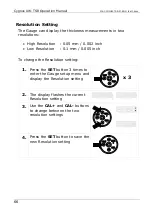
M4-CYG1UW-TSR-M-ENG_Iss11.docx
Cygnus UW-TSR Operating Manual
59
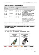
Probe Selection & Specifications
Crystal
Diameter
Frequency
Measurement
Range
Application
13 mm
½ inch
2¼ MHz
3.0
–
250 mm
4
0.12
–
10 inch
This is the standard probe
–
suitable for most
applications.
13 mm
½ inch
3½ MHz
2.0
–
150 mm
0.08
–
6 inch
Suitable for measurement on
thinner sections where
surfaces are relatively rough
6 mm
¼ inch
5 MHz
1.0
–
50 mm
0.04
–
2 inch
The higher frequency and
narrower beam makes this
Probe ideal for measuring
small-bore tubing, thin section
plate and other areas where
access is limited.
13 mm
½ inch
5 MHz
1.0
–
50 mm
0.04
–
2 inch
Ideal for thin sections without
heavy corrosion.
Lower frequency probes offer better penetration on heavy
corrosion/coatings.
Probe Frequency Identification
The frequency of Cygnus probes is indicated by colour:
Old Style
Probes
Inox Remote
Probes
Coloured Probe Face
Coloured Band on
Probe Cap
4
To measure thicknesses on tall thin cylinders or columns the height-width ratio should be no
less than 1.0:0.6 (Height:Width) otherwise side reflections prevent measurement.
Red = 2.25 MHz
Orange = 3.5 MHz
Black = 5.0 MHz


