230
D320 PLC User's Manual
Overview
This appendix describes in detail the user-defined communications protocols supported by the second
program loader port located on the D320 CPU. Through the use of internal Flags (F) and System
Registers (SR), the second port can be configured to support three separate modes of operation; the
D320 program loader port protocol (D320 mode), the MODBUS RTU slave protocol (MODBUS
mode), and the User-Defined ASCII/Binary transmit/receive protocol (UDCP mode).
Port Configuration
Communications port #2 on the D320 CPU module is user-configurable for a variety of protocols,
baud rates, parities, and so on. The port contains line-driver support for both RS232 and RS485
hardware communications. The CPU auto-detects the incoming signal, and uses the correct hardware
protocol as required. Refer to Chapter 4 for a detailed pin-out of the 9-pin D-connector.
Baud rates supported by Comm. Port 2 are 4800 baud to 38,400 baud. The baud rate at which the port
communicates is configured through the use of a bank of dip-switches located on the CPU module,
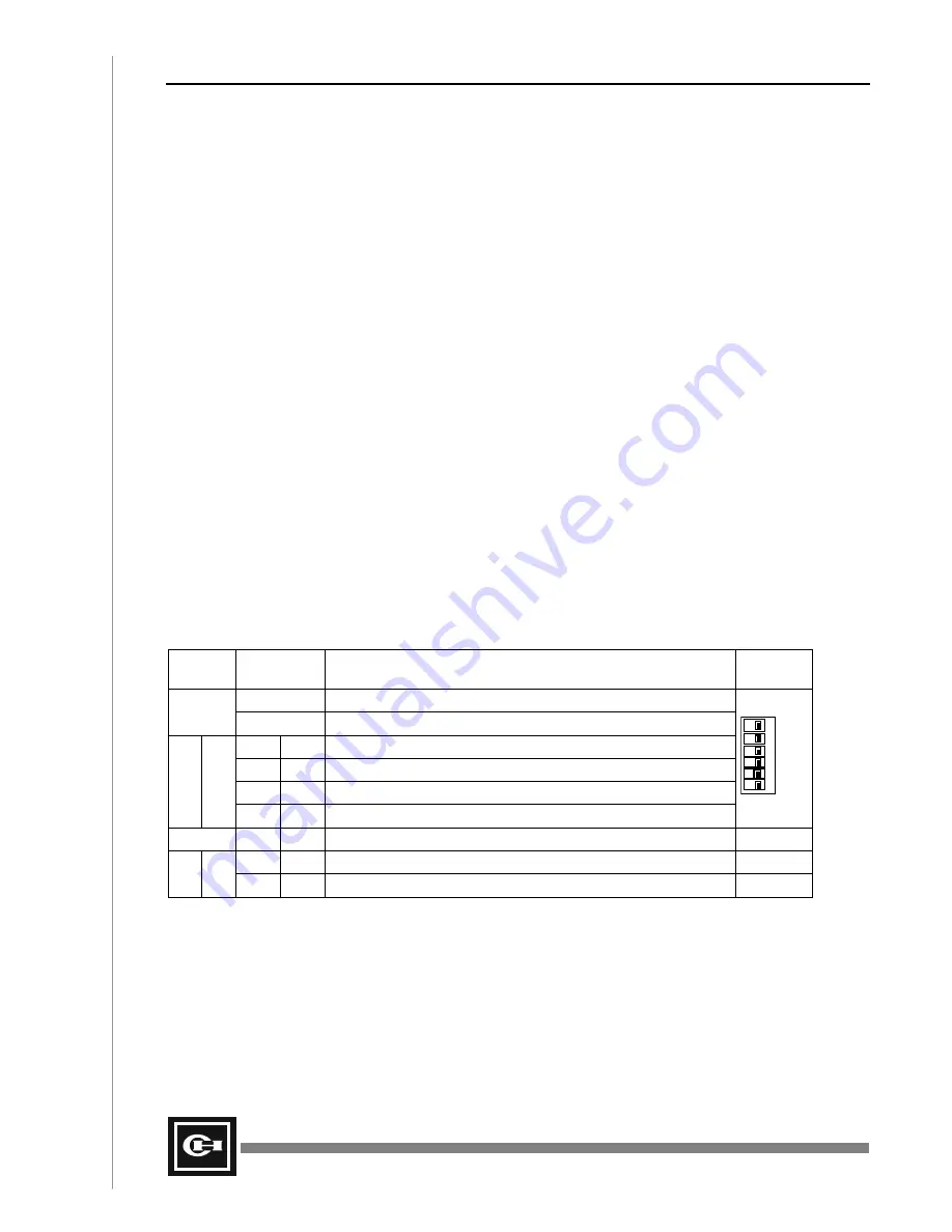
between ports 1 and 2. Table 1 shows the proper dip-switch settings for the given baud rate.
Additionally, when using RS-485 communications, the “nodes” at the end of the RS-485
communications network should always be terminated with impedance matching resistors. These
“Terminating Resistors” match the natural resistance of the communications line, and prevent reflected
voltages from disrupting communications along the line. When the CPU module is at the end of the
communications line, dip-switches 5 and 6 can be used to properly terminate the network. See Table 1
below.
Table 1 – Comm. Port Configuration
Switch
Number
Switch
Position
Function
Diagram
Off
COM1, 9,600 bps
1
On
COM1, 19,200 bps
Off
Off
COM2, 9,600 bps
On
Off
COM2, 19,200 bps
Off
On
COM2, 38,400 bps
2
3
On
On
COM2, 4,800 bps
DIP1
ON
6
5
4
3
2
1
4
Not used.
Off
Off
Terminating resistors for RS485 communications not connected.
5
6
On
On
Terminating resistors for RS485 communications connected.
Summary of Contents for D320 PLC
Page 1: ...D320 PLC User s Manual...
Page 18: ...6 D320 PLC User s Manual...
Page 28: ...16 D320 PLC User s Manual...
Page 34: ...22 D320 PLC User s Manual...
Page 78: ...66 D320 PLC User s Manual...
Page 176: ...164 D320 PLC User s Manual...
Page 210: ...198 D320 PLC User s Manual...
Page 258: ...246 D320 PLC User s Manual...


