1. INSTALLATION AND USE
PRT 80
1
1-
Pin 1
J5
1.1 CONNECTIONS
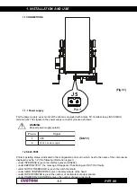
1.1.1 Power supply
For the power supply, every model of the printer is equipped with a male, 90° mobile screw (pitch 5.08mm)
terminal (J5). The signals on the power suppy connector pins are as follows:
WARNING:
Respect power supply polarity.
.
o
n
n
i
P
l
a
n
g
i
S
1
D
N
G
2
y
l
p
p
u
s
r
e
w
o
p
c
c
V
4
2
1.2 SELF-TEST
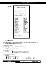
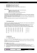
Printer operating status is indicated in the configuration print-out in which, next to the name of the components
displayed (see fig. 1.2), the following information is given:
• under
INTERFACE
is given the interface present (RS232,).
• under
EEPROM TEST ,
the message OK appears if functioning and NOT OK if faulty.
• under NOTCH THERSHOLD is given the notch thershold
• under
HEAD TEMPERATURE
is given the temperature of the head.
• under
PAPER PRINTED
is given the number of centimeters of paper printed.
• under
POWER ON COUNTER
is given the number of power-ups made.
(Fig.1.1)
(Tab.1.1)
Summary of Contents for PRT 80
Page 1: ...PRT 80 Thermal printer for information kiosks and ATMs PRT 80 User Manual www custom it ...
Page 6: ...TABLE OF CONTENTS PRT 80 ii Blank Page ...
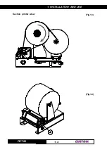
Page 14: ...1 INSTALLATION AND USE PRT 80 4 1 Section printer wiew Fig 1 3 Fig 1 4 ...
Page 16: ...1 INSTALLATION AND USE PRT 80 6 1 Blank page ...
Page 92: ...4 TECHNICAL SPECIFICATIONS PRT 80 4 4 Fig 4 3 Top view Low view Fig 4 4 4 X M3 ...


