CANifier
User’s
Guide www.ctr-electronics.com 10/8/2017
Cross The Road Electronics Page 2 10/8/2017
Table of Contents
1. What is CANifier? .......................................................................................................................................................................... 4
1.1. Features ................................................................................................................................................................................ 5
1.2. Pin Descriptions .................................................................................................................................................................... 6
1.3. Electrical Specifications ......................................................................................................................................................... 7
1.3.1. Voltage Rail Dropout Plots. ........................................................................................................................................... 7
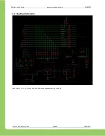
1.4. Electrical Schematic .............................................................................................................................................................. 8
1.5. LEDs ....................................................................................................................................................................................... 9
1.5.1. LED Channel LEDs (3) ..................................................................................................................................................... 9
1.5.2. Status LED States (2)...................................................................................................................................................... 9
2. Installation .................................................................................................................................................................................. 11
2.1. Installing CAN Bus and Power leads .................................................................................................................................... 11
2.2. Wiring Common-Anode LED Strip ....................................................................................................................................... 12
2.3. Wiring remaining signals. .................................................................................................................................................... 12
2.3.1. Sensor examples ......................................................................................................................................................... 13
2.4. Test CANifier assembly and wiring ...................................................................................................................................... 15
2.5. Enclose/Insulate CANifier assembly .................................................................................................................................... 16
3. Phoenix Framework (Software) .................................................................................................................................................. 17
3.1. Software Examples .............................................................................................................................................................. 17
3.2. Status Frame Rates ............................................................................................................................................................. 17
3.3. Custom Platforms................................................................................................................................................................ 17
3.4. HERO LifeBoat / roboRIO Web-based configuration ........................................................................................................... 18
4. Functional Limitations ................................................................................................................................................................. 19
4.1. Future features to be implemented. ................................................................................................................................... 19
4.2. When hot-swapping certain sensors, CANifier may reset. .................................................................................................. 19
4.3. roboRIO Self-test will be added in future. ........................................................................................................................... 19
4.4. Reverse Limit signal is missing ESD diode. .......................................................................................................................... 19
4.5. Silkscreen suggests max input voltage is 33V. Vdd-max is 28V. ......................................................................................... 19
5. Frequently Asked Questions (FAQ) ............................................................................................................................................. 20
5.1. Certain features are not working, but this document indicates they should work. ............................................................ 20
5.2. Signals updates seem slow. There is stair-stepping in my signal plots. .............................................................................. 20
6. Firmware (CRF) Version History .................................................................................................................................................. 21
7. Revision History .......................................................................................................................................................................... 21


