CANifier
User’s
Guide www.ctr-electronics.com 10/8/2017
Cross The Road Electronics Page 16 10/8/2017
2.5. Enclose/Insulate CANifier assembly
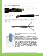
The recommended approach to insulate CANifier is to shroud entire wire assembly in 1” heat shrink tubing.
Insert assembly into one side of a precut heat
shrink tubing.
Heat shrink should cover all
exposed electrical areas of
CANifier and LED strip.
After applying heat to heat shrink tubing, neatly wrap and separate the harnesses into their logical sub groups.
Illustrated below are two pigtails for CAN bus, power leads (to PDP/power source), and wire harness for
PWMs/sensors/etc.
Alternatively, the CANifier can be mounted to a fixed location using a 3D
printed enclosure.
Fixed mounting is accomplished via the two mounting holes in the CANifier.
These holes are 0.125” in diameter nominally, and act as clearance for a 4
-40
or M3 screw. A case for the CANifier in STEP and STL formats is available on ctr-
eletronics.com to facilitate fixed mounting while covering the exposed pads.
Use any length 4-40 or M3 screw to attach the CANifier to your mounting
surface. Ensure that there is no contact between any exposed pads and the
mounting surface. Plastic spacers can be used to isolate the CANifier from the
surface. The CANifier can also be mounted with double-side tape, but ensure
that the tape is nonconductive and that wires are soldered onto the CANifier
before mounting.


