3
Before Operating This Equipment
Read and understand this owner's manual.
Safety & Set-Up Instructions
If your drill is delivered with a shipping bracket, DO NOT install hitch or operate
hydraulics until bracket is completely removed. Damage to drill will result.
Dealer Installation of Hitch - Be sure hitch bolts are torqued equally. DO NOT tighten
one side completely before the other. Failure to follow these instructions could cause
hitch to be off center and drill will not run straight.
Secure implement to tractor drawbar using as large a hitch pin as will allow. A large
bolt with locking nut or castle nut is recommended. DO NOT use a hairpin or wire to
secure hitch pin. Residue may catch and remove these devices. ALWAYS SECURE
DRILL TO TRACTOR USING THE SUPPLIED SAFETY CHAIN.
Make sure 3-point linkages are raised completely to clear hitch.
DO NOT attempt to remove the hydraulic cylinder unless you have taken the
precautions described on page 4 of this manual. Serious injury or death could
occur if the correct procedure is not followed!
If your tractor does not already have a lighting receptacle, install one. Always plug in
the drill lighting system to a correctly wired tractor and USE for transport safety.
Your drill may weigh more than the towing vehicle. The drill is not equipped with
brakes. EXERCISE EXTREME CAUTION ! Maximum allowable speed - 25 mph.
If your drill is equipped with hydraulic markers, always attach safety chains before
transporting.
Always install transport lock to hydraulic cylinder before transporting.
Remove transport lock from lift cylinder before attempting field operation.
Never have more than 391 lbs. per section on the walkboards without drill securely
attached to tractor or towing vehicle.
Check lug nuts or bolts. Torque to 100 ft. lbs. after approximately one mile and
periodically after.
After approximately 10 hours, make sure tool bar bolts, wheel bolts, presswheel bolts,
etc. are tight. Check tool bar bolts every 10 to 15 hours. Tool bar bolts must stay
tight. Failure to comply could cause damage to tool bar and main frame in the form
of egg shaped holes.
NEVER ALLOW ANYONE TO RIDE THE DRILL!
Summary of Contents for 4600 Series
Page 1: ...4600 SERIES ALL PLANT DRILL 09 03 605717 ...
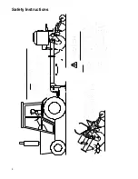
Page 6: ...4 Safety Instructions ...
Page 7: ...5 Safety Instructions ...
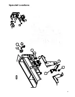
Page 19: ...17 Sprocket Locations ...
Page 20: ...18 ...
Page 34: ...32 Grain Box 10 ...
Page 36: ...34 Grain Box 15 20 ...
Page 44: ...42 All Plant Opener Assembly ...
Page 46: ...44 Gear Box Assembly 10 ...
Page 48: ...46 Gear Box Assembly 15 20 ...
Page 61: ...58 a Harrow Layouts 10 Drill 7 Spacing 10 Drill 10 Spacing ...
Page 62: ...58 b ...
Page 63: ...59 15 Drill 8 Spacing 15 Drill 7 Spacing Harrow Layouts ...
Page 64: ...60 15 Drill 10 Spacing 20 Drill 7 Spacing Harrow Layouts ...
Page 65: ...61 20 Drill 8 Spacing 20 Drill 10 Spacing Harrow Layouts ...
Page 66: ...62 15 Legume ...
Page 68: ...64 20 Legume ...
Page 71: ...67 Light System ...
Page 72: ......
Page 73: ...69 Fertilizer Unit ...
Page 76: ...72 4615 Sprocket Locations Fertilizer Unit ...
Page 78: ...74 4615 Drive Assembly Fertilizer Unit ...
Page 80: ...76 4615 Gear Box Fertilizer Unit ...
Page 82: ...78 4615 Box Bottom Assembly Fertilizer Unit ...
Page 84: ...80 4600 All Plant Feed Tubes Fertilizer Unit ...
Page 86: ...P O Box 1438 Dodge City Kansas 67801 620 227 7106 ...


