8
Field Operation
Recommended Operating Speed
Operating speeds of 4-7 mph will provide
optimum results from your All Plant drill. Con-
ventional field conditions can warrant speeds in
the upper end of the range. High levels of
"tough" residue due to morning dew or recent
moisture, rough field conditions, rocky fields, or
hard ground may require lower speeds for
adequate performance.
Recommended Adjustment Procedure
Setting your All Plant drill requires adjustments
be made in a particular order to ensure the
opener will work properly. You will find it much
easier to set the drill if adjustments are made in
the following order:
1.
Level the drill
2.
Set toolbar rotation
3.
Set down pressure
4.
Set seed depth
Leveling the Drill
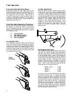
It is important to level the drill from front to back
first. The tongue and box should be as close to
level as you can get it by changing the drawbar
height on the tractor (on offset drawbars), or by
repositioning the clevis or mono hitch mounting.
Any time a different tractor is hooked to the drill
you should recheck level.
Clevis
Positions
Toolbar Adjustment
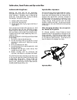
After the drill is leveled, rotation of the toolbar
must be set. Using the screw adjustable stop
on the lift cylinder, adjust rotation of the toolbar
until the 2" x 4" tubing the openers are mounted
on is perpendicular to the ground. Adjustment
range of the presswheel depth quadrant will be
affected if the toolbar does not rotate far
enough or goes beyond perpendicular. If the
toolbar is not set correctly, the opener travel
range will not allow for penetration into low
areas or provide clearance when meeting
obstructions.
Setting Down Pressure
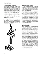
The parallel linkage opener design assures the
operator the opener blades and presswheel
operate on the same level throughout the range
of up and down travel. Due to the location of
the down pressure spring, the pressure applied
to the opener remains relatively constant in the
entire range of travel. Changing the spring
position from the first (top) notch to the last
(bottom) notch provides 4 different levels of
force. Each notch represents approximately
these amounts of down pressure:
Notch 1 (top)
140#
Notch 2
275#
Notch 3
400#
Notch 4
525#
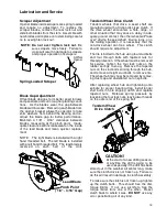
It may be necessary to add ballast to the drill in
the third or fourth notch. In order that all the
opener springs are able to achieve the down
pressure selected, the total weight of the drill
must equal that amount of pressure times the
number of row units on the drill. The parallel
linkage arms should have a "live working ac-
tion" during field operation. Setting the drill for
too much down pressure without adequate
weight will reduce the ability of the opener to
flex and give good performance.
Summary of Contents for 4600 Series
Page 1: ...4600 SERIES ALL PLANT DRILL 09 03 605717 ...
Page 6: ...4 Safety Instructions ...
Page 7: ...5 Safety Instructions ...
Page 19: ...17 Sprocket Locations ...
Page 20: ...18 ...
Page 34: ...32 Grain Box 10 ...
Page 36: ...34 Grain Box 15 20 ...
Page 44: ...42 All Plant Opener Assembly ...
Page 46: ...44 Gear Box Assembly 10 ...
Page 48: ...46 Gear Box Assembly 15 20 ...
Page 61: ...58 a Harrow Layouts 10 Drill 7 Spacing 10 Drill 10 Spacing ...
Page 62: ...58 b ...
Page 63: ...59 15 Drill 8 Spacing 15 Drill 7 Spacing Harrow Layouts ...
Page 64: ...60 15 Drill 10 Spacing 20 Drill 7 Spacing Harrow Layouts ...
Page 65: ...61 20 Drill 8 Spacing 20 Drill 10 Spacing Harrow Layouts ...
Page 66: ...62 15 Legume ...
Page 68: ...64 20 Legume ...
Page 71: ...67 Light System ...
Page 72: ......
Page 73: ...69 Fertilizer Unit ...
Page 76: ...72 4615 Sprocket Locations Fertilizer Unit ...
Page 78: ...74 4615 Drive Assembly Fertilizer Unit ...
Page 80: ...76 4615 Gear Box Fertilizer Unit ...
Page 82: ...78 4615 Box Bottom Assembly Fertilizer Unit ...
Page 84: ...80 4600 All Plant Feed Tubes Fertilizer Unit ...
Page 86: ...P O Box 1438 Dodge City Kansas 67801 620 227 7106 ...


