background image

The 

outgoing

, inner conveyor bolt is in

the block on the machine. It can’t be 
removed due to interference with the
motor and transmission flange. Figure H.
Fit the outgoing conveyor just as you did
the ingoing side.

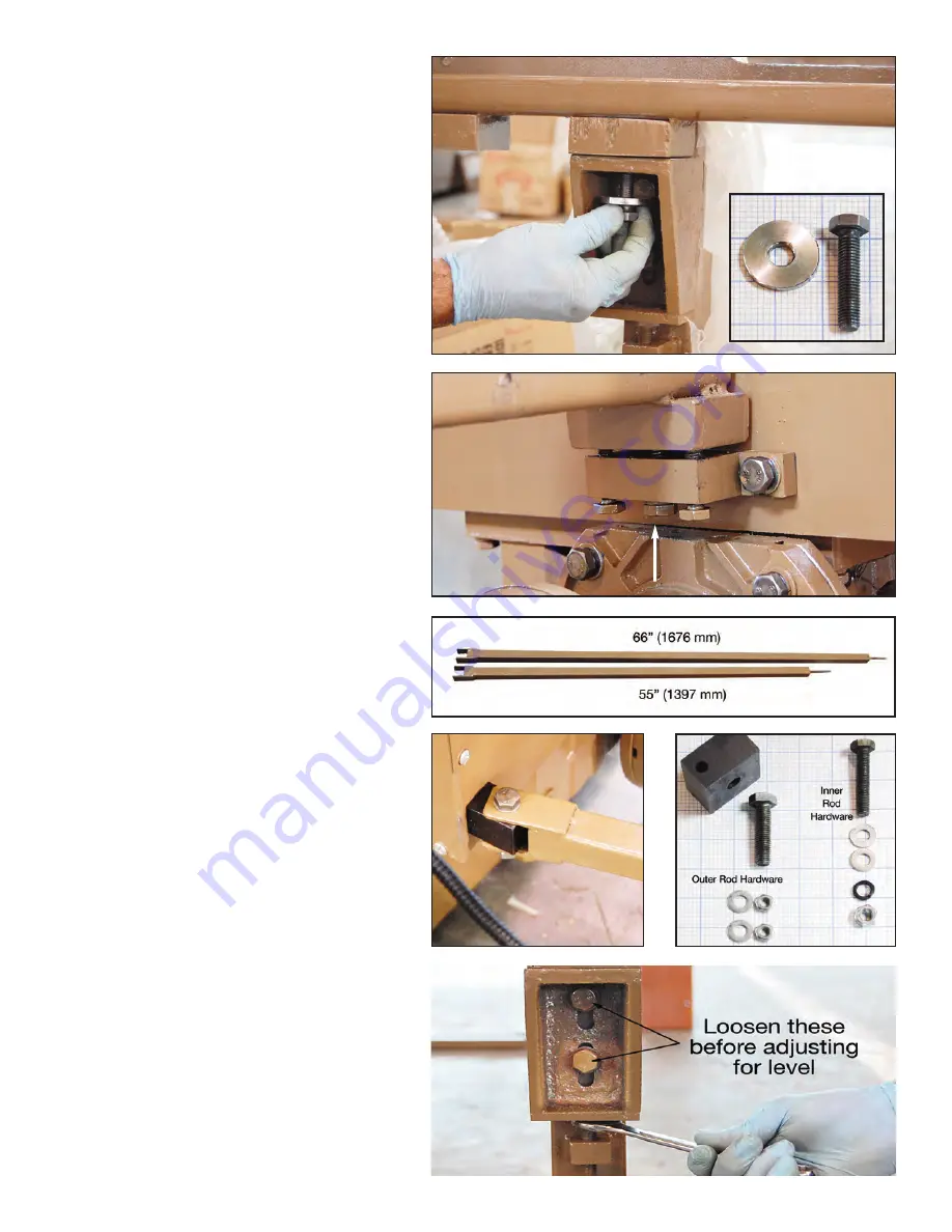
The Pull Rods that keep the conveyors
aligned are unequal lengths.
• Ingoing (R) side rod is 66” (1676 mm)
• Outgoing (L) side rod is 55” (1397 mm)

Fit the rods with the hardware and
blocks shown in Figures J and K. Before
tightening the rods, be sure the conveyors
are perpendicular to the machine so
glass will run straight into and out of the
machine.

Level the conveyors with the outer bolts
as shown in figure L. Also see Figure 10
in the manual. Now the Pull Rods can be
hand tightened.

Install the timing belts over the outer 
pulleys and adjust the tension as shown
in Figure M (next page). Be sure the belt
is centered in the pulley and not riding
on the edge. The belt should be tight
enough that it is flat along the top run.
About 1/2” (13mm) of clearance at the
center of the belt run is normal. Figure N
(next page). Tighten the axle nuts on the
outside pulleys. Figure M

The wooden conveyor covers can be 
refitted now. Use the black Allen socket
head bolts.

Figure F

Figure H

Figure G

Figure J

Figure K

Figure L

Pull Rods

Summary of Contents for SM5C

Page 1: ......

Page 2: ...parts list and diagrams in back of this manual 3 Position Machine Body in place see Fig 7 14 4 Install leveling feet on main Body and adjust for level page 6 5 Install and level ingoing conveyor see F...

Page 3: ...S MANUFACTURE SELLER S LIABILITY TO BUYER HEREUNDER IS LIMITED TO SUCH WARRANTY AS THE MANUFACTURER MAKES TO SELLER BUT IN NO CASE GREATER THAN 12 MONTHS FROM DATE OF SHIPMENT BY SELLER LIMITATION OF...

Page 4: ...s in this manual and to regularly follow procedures of maintenance which will allow you to obtain a higher degree of reliability safety and durability of the product This manual contains several advis...

Page 5: ...area clean and orderly as unorganized work areas encourage accidents Before starting verify the condition of the machine Check the standard operation and for broken and or damaged parts Replace all br...

Page 6: ...angle 45 Max arris width 2 5mm 3 32inch Max grinding amount of flat edge 2 5mm 3 32inch 4 Height of input conveyor 850mm 33 5inch 5 Glass feeding speed 0 5 3 0m min 20 120inch min 6 Overall dimension...

Page 7: ...guard Raise the low side by turning the square bolt heads clockwise until the machine is level side to side Now adjust the rear feet to maintain a 5 degree tilt back This is the standard angle to keep...

Page 8: ...r Source Switch with Indicator Light 2 Grinding Motor Ampere Meters 3 Arris Seam Motor Ampere Meters 2 4 Polish Motor Ampere Meters 2 5 Motor Overload Indicator Light 6 Conveyor Ampere Meter 7 Voltage...

Page 9: ...tioned adjustment position that you recorded Grinding Testing 1 Now all the wheels are at Zero grinding position You can now adjust the wheel position according to the grinding amount desired In norma...

Page 10: ...middle of the oil gauge or have the box full 4 Grease the bearings gears and sprockets of the right and left gearbox every 3 or 4 months of operating 5 Change the water in the coolant tank periodicall...

Page 11: ...ear etc 03 SE5M F2 Output Conveyor 1 With wooden gear etc 04 38 1 XH4289 425 2mm PU Timing Belt 2 05 SE5M F10 Pull Rod 2 06 SE5M F11 Middle Pillar 2 07 SE5M F12 Rack Pillar 2 08 2145mm Roller Strip 4...

Page 12: ...Box List Tools No Item Description Qty Remark 01 Tool Box 1 02 S 10 14 17 19 24 Sockets Each 1 03 250mm Ratchet Handle 1 04 250mm Long Extension 1 05 125mm Short Extension 1 06 S 10 14 17 19 24 Combo...

Page 13: ...LIARY CONTACTOR 1 47013271 OVERLOAD RELAY 3US5040 1J 1 47013272 OVERLOAD RELAY 1 0 1 6A 1 47013273 OVERLOAD RELAY 4 0 6 3A 1 47013274 FUSE 6A 1 47013275 INDICATOR LAMP G23 1 47013276 BUTTON SWITCH E S...

Page 14: ......

Page 15: ......

Page 16: ......

Page 17: ......

Page 18: ......

Page 19: ......

Page 20: ......

Page 21: ......

Page 22: ......

Page 23: ......

Page 24: ......

Page 25: ......

Page 26: ......

Page 27: ......

Page 28: ...ls Annex to User Manual The following assembly details will be of help when assembling the SM5C June 2011 Some construction details may have changed since the photos were taken but the assembly method...

Page 29: ...th 83 2108 mm A black rubber roller is at the out side end of each conveyor Remove the wooden conveyor covers The vertical supports are the same for either side of the machine They will require two sh...

Page 30: ...l run straight into and out of the machine Level the conveyors with the outer bolts as shown in figure L Also see Figure 10 in the manual Now the Pull Rods can be hand tightened Install the timing bel...

Page 31: ...utgoing left side 2 78 1981 mm top or middle 1 73 1854 mm bottom Attachment bolts will need to be slid into the tracks on the back side Place 2 of the 3 1 8 79 mm plated bolts Figure S in each lower r...

Page 32: ...you After connecting the power supply have the electrician check for proper voltage indicated on the Volt Meter on the control panel and check the operation of the coolant pump as follows Be sure the...

Reviews: