Crestron
TPS-ENET
Ethernet Card for TPS/Tilt Panel
12. Hold the touchpanel base cover in place and position the
touchpanel face down onto a padded surface to prevent
scratching of the screen.
13. Re-install the
eight
base cover screws to
finger-tight
then,
using a #1 Philips screwdriver, tighten an additional
1/8-turn
.
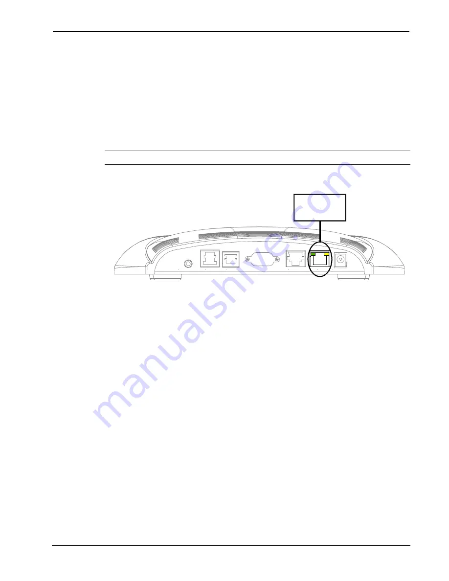
14. Refer to the diagram below and attach an appropriate cable
(not supplied) to the LAN port as shown.
NOTE:
For Ethernet connections, refer to table on page 3.
Attach Ethernet Cable
HEADPHONES
AUDIO
RGB
LAN
RS-232
NET/VIDEO
24VDC 2.0A
CABLE
FROM
ETHERNET
15. Reconnect all cables to the appropriate touchpanel rear panel
ports.
16. If the optional external AC power pack is utilized, connect the
plug of the power pack to the touchpanel rear port labeled
24VDC 2A.
Obtaining Communications
To setup the touchpanel for Ethernet communication, it is necessary to
first obtain communication with the device. Communication with the
touchpanel can be established via the local RS-232 port or the host
control system via remote console mode (Cresnet).
To obtain communication with the touchpanel via RS-232, refer to the
following procedure. To obtain communication with the touchpanel via
the host control system, refer to the remote console procedure beginning
on page 12.
Operations & Installation Guide - DOC. 6016
Ethernet Card for TPS/Tilt Panel: TPS-ENET
•
9


