Touchpanel Media Centers
Crestron Isys i/O
™
TPMC-15/17 Tilt Series
QM versions can select whether the display is turned off, the QM output is turned
off, or both the display and the QM output are turned off.
Cable Management
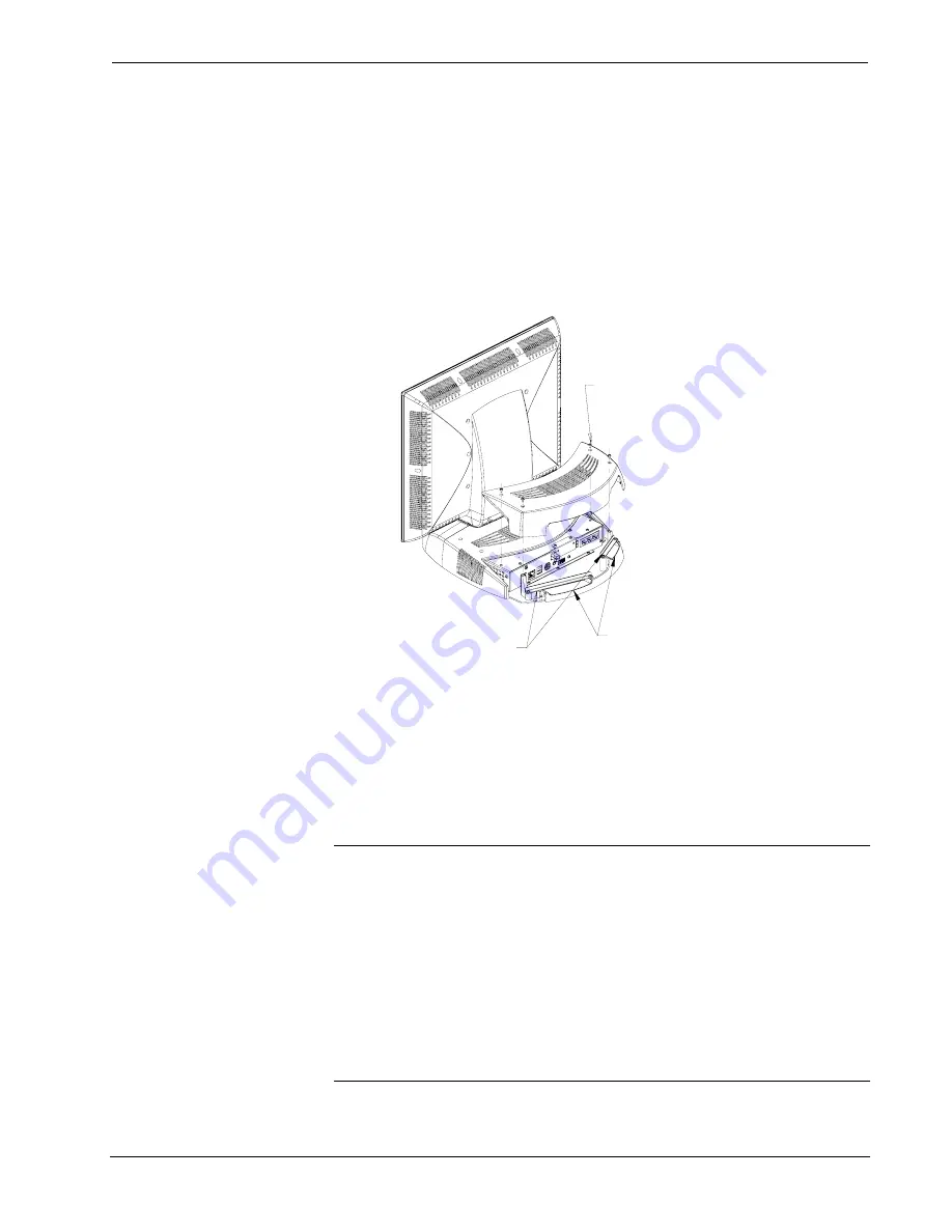
All versions of the TPMC-15 and TPMC-17 use a built-in strain relief to prevent
accidentally disconnecting vital cables and provide strain-relief to connectors on
cables and the touchpanel. Refer to the following illustration to use the built-in strain
relief mechanism to secure cables to the touchpanel.
Using Strain-Relief Mechanism
USE THESE SCREWS AND
METAL BRACKETS TO CLAMP
DOWN INPUT/OUTPUT CABLES
ROUTE CABLES THROUGH
THESE VALLEYS
REMOVE THESE SCREWS
(QTY. 4) TO REMOVE PLASTIC
COVER FOR ACCESS TO
INPUT/OUTPUT PANEL
Hardware Hookup
Make the necessary connections as called out in the following illustration. Refer to
“Network Wiring“ on page 21, “CAT5 Wiring (CH Versions Only)” on page 23, and
“QM Network Wiring (QM Versions Only)” on page 23 before applying power. If
the TPMC-CH-IMC is to be used (CH versions only), refer to the latest revision of
the TPMC-CH-IMC Operations Guide (Doc. 6345) for more information.
CAUTION:
Do not apply excessive pressure to the touchscreen display during
handling. Doing so can crack the screen and damage the touchpanel.
CAUTION:
PCMCIA cards should be installed face down.
NOTE:
To prevent overheating, do not operate this product in an area that exceeds
the environmental temperature range listed in the table of specifications.
NOTE:
The maximum continuous current from equipment under any external load
conditions shall not exceed a current limit that is suitable for the minimum wire
gauge used in interconnecting cables. The ratings on the connecting unit's supply
input should be considered to prevent overloading the wiring.
48
•
Touchpanel Media Centers: Crestron Isys i/O™ TPMC-15/17 Tilt Series Operations
Guide - DOC. 6344


