John Deere Air Reel Owner’s Manual
46
ASSEMBLY
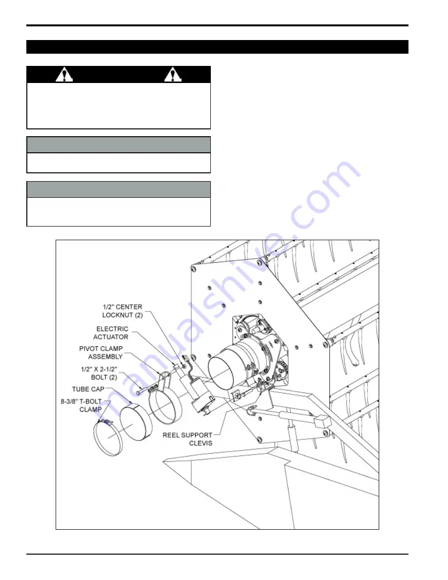
4.23 MANiFOLD TiLT
Slide the pivot clamp assembly over the LH end of
the manifold, and position it next to the reel support
bracket. Do not tighten the clamp at this time.
If using a left hand drive kit, skip to Step 3. Otherwise,
place the tube cap over the end of the manifold tube
and secure with the t-bolt clamp.
Bolt the stationary end of the electric actuator to the
clevis on the reel support bracket (Figure 65).
Rotate the manifold so the line of sight along the air
tubes is directed just behind the cutterbar (See sec-
tion 5.5).
Extend the actuator 1/2 the length of the full extension
(approx. 2”).
Bolt the actuator to the clevis on the pivot clamp as-
sembly.
Tighten the pivot clamp assembly around the manifold
tube.
1.
2.
3.
4.
5.
6.
7.
Figure 65, Manifold tilt
WARNiNG
Place all controls in neutral or off, stop combine engine,
set parking brake, remove ignition key, set cylinder
stops, wait for all moving parts to stop, then properly
block machine before servicing, adjusting, repairing or
unplugging.
NOTE
Be sure the reel can be rotated by hand before attach-
ing the actuator.
NOTE
The pivot clamp assembly may serve as a clamp for the
tube cap in some instances. In this case, you would not
use the 8-3/8” t-bolt clamp.


