11
32. Trim the casing half gaskets fl ush with casing at end
of
stuffi ng box using a putty knife, fi le, etc.
33.
Mechanical seal pumps:
Remove rag or towel from
between seal cap and rotating element of seal that
was placed here in Step 15. Slide seal element into
place, check to be sure seal faces are clean, and
that the sealing washer is properly positioned in
retainer. Push seal cap and seal cap gasket in
evenly far enough to install seal cap bolts and washers.
Care must be taken to turn both bolts equally to
prevent cocking the seal cap and chipping or cracking
the carbon sealing washer. Check to make sure
gasket is in proper position. Note that these bolts only
need to be tight enough to compress gasket to seal.
34.
Pack Pumps:
Install the gland halves (Note: These
are in sets and marked as such and cannot be
mixed. The one with the hole goes on bottom), gland
washers and nuts. Tighten nuts down fi nger tight.
Be sure the gland has entered the box at least 1/8”.
If the packing will not compress to allow this, remove
one ring of packing. The breaking-in period of the
packing is more important in the satisfactory
performance of a stuffi ng box. When the pump
is returned to service, additional care must be given
the packing box to insure proper packing life. It is
necessary to allow 60 to 100 drops leakage per
minute through the packing for lubrication purposes.
If
the
fl ow rate is other than this, the gland nuts
should be loosened or tightened one fl at (1/16 turn)
at a time to acquire the correct leakage (both nuts
must be turned equally to prevent cocking the gland)
allow at least ten minutes between adjustment for
the leakage rate to stabilize. When in doubt, choose
the greater leakage rate, since overly tightened
packing will ruin the packing as well as the sleeve.
35. Install relief cooling, abrasive separator, fl ush lines,
vent cock, drain plug and other fi ttings that were
removed during disassembly.
36. Open vent cock to evacuate air. Slowly open suction
valve, when air has evacuated close vent cock and
fully open suction valve. Open discharge valve
to its original position. Check for leaks and turn
rotating assembly. Never start a pump until all air
and vapor has been evacuated. Without fl uid around
it, the mechanical seal may be ruined within a few
seconds of operation. It is possible that the
mechanical seals may drip the fi rst few minutes to an
hour of operation.
39. Install coupling sleeve, adjust and align coupling.
Refer to alignment procedure section.
40. Install coupling guard
41. Turn power to pump on. Start and run pump
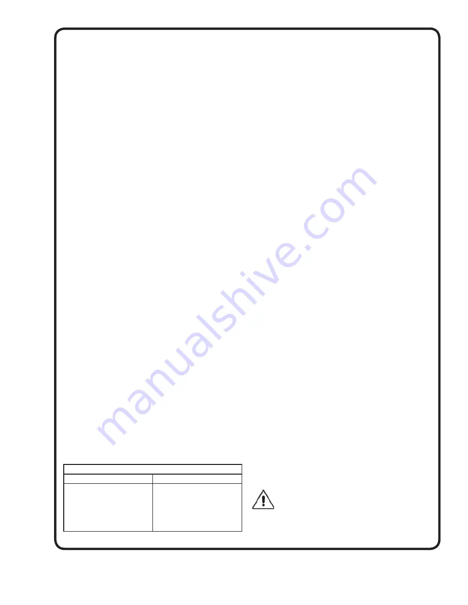
TORQUE REQUIREMENTS
SIZE
FOOT-POUNDS
3/8-16
1/2-13
5/8-11
3/4-10
7/8-9
1-8
21.7
43.5
86.0
152.0
222.0
307.0
FOOTNOTE:
The rotating assembly can be adjusted by
loosening the three bolts that holds the bearing housing to
lower case half on one end or the other, or both. Lift up on
bearing housing and snug bottom bolt, then using a rubber
hammer, lightly tap housing while turning shaft. Repeat
until best position is found, then tighten all bolts.
5. DOUBLE-WEAR RING IMPELLERS:
Remove -
Wear rings are pressed and bolted on and must
be removed with puller or by drilling through the width of
the wear ring and removing with a chisel after the wear
ring locking screws are removed. Wear ring locking screws
can be removed by center punching and drilling out using
a 7/32” drill.
Install -
Install wear rings onto impeller hubs. Drill through
each wear ring and impeller hub in two places 180° apart,
using a number 7 drill, tap holes with 1/4-20UNC tap
stopping 1 or 2 threads short of tapping through. Thread
screws into tapped holes until tight or fl ush with inside of
impeller hub. Cut screws off fl ush with outside diameter of
wear ring and fi le smooth any burrs or protrusions.
6. CHANGE ROTATION:
Follow disassembly instructions Steps 1 thru 24. Turn both
impellers and interstage diaphragm around and slide back
onto shaft. The mark put on impeller in Step 16 should
be opposite the coupling (driver) end of shaft. Follow
reassembly instruction Steps 1 thru 10, Steps 17 thru 39.
There is only one correct way for impeller to go in casing.
If pump is mounted on base, unbolt and turn casing
around 180°.
7. SEAL REPLACEMENT (Inboard):
Follow disassembly instructions Steps 1 thru 4, remove
fl ush line to seal cap only, 5, 6 remove three motor
mounting bolts and turn motor enough to allow for coupling
removal, 7, 16 thru 21.
Follow reassembly instructions Steps 5, 6, 7, 9, 10. 16, 17,
22, 28, 32, 34, 35, put motor back into place, 36 & 27.
8. SEAL REPLACEMENT (Outboard):
Follow disassembly instructions Steps 1, 2, 3, remove
fl ush line to seal cap, 7, 25 thru 28, then 18 thru 21.
Follow reassembly instructions Steps 5, 6, 7 thru 15, 21,
32, 34, 35.
9. SHAFT SEAL - TYPE 1 INSTALLATION
Remove top half of the casing. After determining size and
type of pump from name plate, fi nd setting location of
seal collar, either X, Y, or Z, from Table 1. If the seal collar
needs resetting, rotate it 30° before tightening set screws.
IMPORTANT ! - DO NOT ATTEMPT TO
REINSTALL ANY USED PARTS OF THE SEAL,
EXCEPT THE SPRING AND COLLAR.
Summary of Contents for Deming 5260 Series
Page 7: ...7 Figure 3 ...
Page 22: ...Notes ...


