


9
2. PACKING BOX
The packing glands should be adjusted occasionally to
insure proper packing lubrication. A slow dripping through
the gland is recommended for good lubrication and long
packing and shaft sleeve life.
When installing new rings of packing, clean packing box
and inspect parts for any damage. If the shaft sleeve is
worn or grooved, it should be replaced. New packing will
not do an adequate sealing job on a worn shaft sleeve.
Insert two new rings of packing in front of lantern ring.
Stagger joints to minimize leakage.
Tamp each ring in place. Replace lantern ring. Add two
rings of packing behind lantern ring. Replace gland and
bolts, rotate shaft and tighten gland securely. Loosen the
gland and add the fi nal ring of packing. Be sure lantern
ring is positioned to receive lubrication through orifi ce.
Tighten nuts securely to seat packing and rotate shaft.
After rotating several turns, loosen nuts to fi nger tight for
starting.
3. DISASSEMBLY
The following procedure is for complete disassembly of
the pump. If complete disassembly is not necessary, use
only those steps which apply.
1. Shut off and lock put power to motor.
2. If hot liquids are being pumped, care should be
taken so personal injury is not incurred during
disassembly.
3. Totally depressurized pump and associated piping
by closing suction and discharge valves, to isolate
pump from system. Slowly open vent cock and then
remove drain plug from casing.
4. Remove all relief cooling, fl ush lines from pump.
5. Remove coupling guard
6. Loosen coupling set screws. Move coupling hubs
back and remove coupling sleeve.
7. Remove seal cap bolts by alternating the loosening
of the bolts. Exercise care to not cock the seal cap,
which could chip or crack the carbon seal face.
(Pack pumps remove packing gland).
8. Remove case rollpins. (Used to align upper and
lower
halves).
9. Using some type of overhead lifting device, (a
frame, come a long chain fall, etc) hook onto the
two eyebolts or lifting lugs on top half of casing.
10. Remove bolts holding casing halves together. Turn
jackscrews in to separate the casing halves.
11. Set top half out of the way on a piece of cardboard
or wood, taking care not to scratch gasket surface.
12. Place casing gasket, as well as all other gaskets in
water to keep them from drying out and shrinking
13. Check seal setting (distance from machined surface
at the end of the stuffi ng box area to the seal collar).
This will need to be known to reset collar in the
proper position, if disassembly requires removal of
collar. (See Chart “Construction Details”).
14. Using overhead lifting device, hook onto rotating
assembly with nylon straps or rope, to not scratch
shaft. Remove bolts holding bearing housing to
pump casing. Remove rotating assembly from casing.
15. Mark impeller on coupling side , so if required to
remove from shaft, it will be reassembled correctly.
16. Remove coupling hub from pump shaft (may
require use of a gear or wheel puller). Remove
coupling key. (This is inboard side).
17. Remove three capscrews holding bearing cap and
bearing housing together. Remove bearing housing
(tap off using rubber hammer). Using a gear or wheel
puller, pull bearing off of shaft.
18. Remove bearing cap and water defl ector (rubber
slinger) from shaft.
19. Loosen set screws in sleeve lock nuts, using a
spanner wrench. Remove (when used).
20. Remove seal cap. (Stationary seal seat is
pressed
in).
21. Remove rotating seal assembly. (Packing and
packing bushing on pack pumps).
22. Slide shaft sleeve off
23. Remove both impellers and interstage diaphragm,
impeller key and casing rings.
24. Remove three capscrews holding bearing cap and
bearing housing together (outboard). Remove
bearing housing (Tap off using rubber housing).
25. Remove retaining ring (bearing snap ring).
26.
Remove bearing (outboard) using gear or wheel puller.
27. Remove thrust collar. (Remove bearing cap before
thrust collar on verticals).
28. Repeat Steps 20 through 25.
4. REASSEMBLY
The following procedure is for the complete assembly of
the pump. This procedure must be followed for satisfactory
operation. If pump is not completely disassembled, use
only the steps that are applicable.
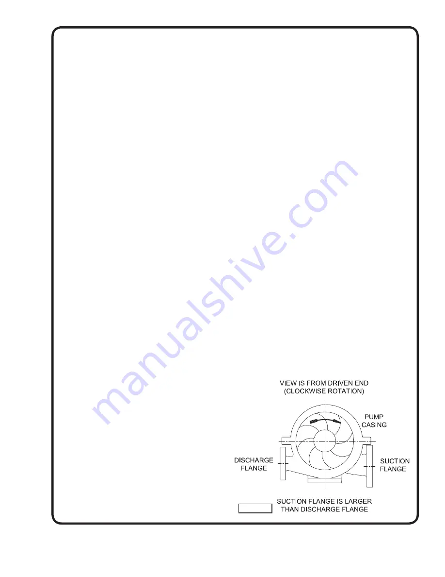
1. Install both impellers and interstage diaphragm,
with gasket between impellers. Make sure impeller
is installed on shaft the same way it came off, per
mark put on it during disassembly. (Double check
vane curvature as indicated as shown in Figure 4.
Figure 4
Summary of Contents for Deming 5260 Series
Page 7: ...7 Figure 3 ...
Page 22: ...Notes ...


