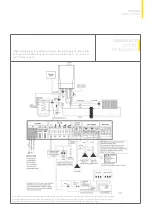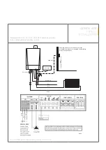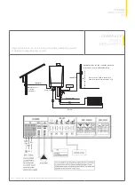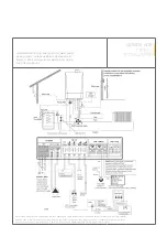
BOILER CONTROLS
The Quinta Ace range can be controlled using a number of
methods – other examples are given below. Scheduling using
the integral Mk3 controller in conjunction with the recommended
Outside / Room sensor when connected to the CB-01 control
board. Other examples are given below. Please contact our
sales or technical departments for further options.
MODULATING (TWO WIRE CONTROL)
When using the optional Remeha compensating controllers the
heat output modulates between the minimum and maximum
value on the basis of the boiler flow temperature sensor. This
applies to both single and multiple boiler installations, under the
dictates of a room and/or outside temperature sensor.
iSense Pro
– multi-boiler multi zone optimising/compensating
controller can control up to ten boilers, two heating zones either
VT or CT and one domestic hot water circuit. Information on
the iSense Pro controller can be obtained from the installation
manual and the suggested wiring and controls schematics for
the controller.
Also, can be used as a boiler sequencer with a 0-10V dc
analogue input signal from a remote BMS controller. Managing
a primary or secondary heating circuit with up to 10 boilers.
The control is temperature dependent only i.e. 5V = 50°C flow
temperature providing lead / lag control, subject to the settings
within the controller.
iSense controller
– single-boiler (option for multiple boiler)
single zone optimising/compensating controller.
Remeha MC4
– in conjunction with the iSense controller can
provide step control for multi-boiler installation of up to four boilers.
ON/OFF VOLT FREE CONTROL FROM A THIRD
PARTY INSTALLER
Connect a two-wire cable to terminal OT / On-Off which must be
a volt free connection from the third party controller.
Analogue control (0-10V dc)
The heat output modulates between the minimum and the
maximum values on the basis of the voltage supplied by an
external analogue (0-10V) input.
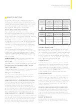
ANALOGUE OUTPUT – TEMPERATURE CONTROL
The 0-10V signal controls the boiler flow temperature between
0°C and 100°C. This control modulates based on the flow
temperature, whereby the heat output varies between the
minimum and maximum values based on the flow temperature
set point calculated by the controller sent by the BMS e.g: 6.4V =
64ºC. A jumper 2 (see table opposite) on the interface is used to
select either temperature control or heat output control (%).
ANALOGUE OUTPUT – CAPACITY CONTROL (%)
The 0-10V signal controls the boiler output between 0% and 100%
of its total capacity (kW). The minimum and maximum values are
limited. The minimum output is linked to the boiler’s modulation
depth. The output varies between the minimum and maximum
value on the basis of the value determined by the controller.
SYSTEM / SHUNT PUMP
A shunt pump can be connected to the boiler via the integral
CB – 01 PCB (maximum input 300VA). If the pump requires more
than this, terminals can only be used to switch a pump relay. The
pump should be fitted on the heating return connection and be
as close to the boiler as possible. A system pump can also be
connected to the boiler via the integral SCB-01 (refer to page 24,
SCB-01 Relay Load data for maximum load).
SYSTEM WATER
Before operation, the system should be cleaned and flushed
(according to BS 7593 (2006) and filled with mains cold water.
Suitable chemicals and their use should be discussed with
specialist water treatment companies in respect to aluminium
heat exchangers. For further information “Remeha Water Quality
Regulations” is available from
remeha.co.uk
The recommendations in the document must be followed.
FROST PROTECTION
Install the boiler in a frost-free room. The built-in frost protection
system is activated as follows: below 7°C – system pump is
switched on if connected to the boiler. Below 3°C – boiler is
switched on, when the flow temp reaches 10°C the boiler and
pump switch off. Note: This control is designed to protect the
boiler – for full system protection use a frost thermostat or a
weather compensator.
REMOTE ALARM AND BOILER RUN INDICATION
As standard the boiler is supplied with the integral smart control
board SCB-01. This has two potential-free contacts, Status
/ Function can be configured as required. Depending on the
setting, a common alarm and boiler run signal can be transmitted
by the boiler.
SAFETY INTERLOCKS
As standard the boiler is supplied with shutdown (BL) and
release (RL) inputs via the main standard connections board
CB-01.
JUMPER 2
INPUT
SIGNAL (V)
TEMPERATURE A
DESCRIPTION
0-1.5
0-15
Boiler off
1.5-1.8
15-18
Hysteresis
1.8-10
18-100
Temp required
JUMPER 2
INPUT
SIGNAL (V)
HEAT OUTPUT (%) DESCRIPTION
0-2.0
(1)
0-20
Boiler off
2.0-2.2
(1)
20-22
Hysteresis
2.0-10
(1)
20-100
Heat output
requested
%
(1) Dependent on the minimum modulation depth (set speeds, standard 20%).
29
ELECTRICAL INSTALLATION
AND BOILER CONTROLS
Summary of Contents for Quinta Ace 115
Page 1: ...QUINTA ACE RANGE ...
Page 70: ......


