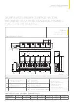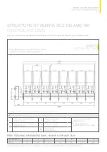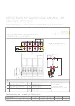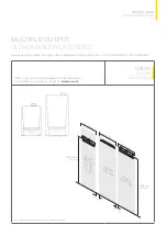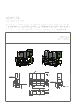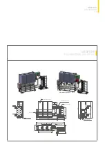
Free-standing frame configuration.
KEY
A
System flow; connection DN 100
or 125/DIN 2631 (8 holes)
OV
Low loss header
DN 65 = 633mm
DN 100 = 643mm
Gas supply connection
DN 50 or 65/DIN 2633 (4 holes)
Air inlet/flue gas discharge
concentric connection
Quinta Ace 30/45 = 80/125mm
Quinta Ace 55/65/90/115 = 100/150mm
B
System return; connection DN 100
or 125/DIN 2631 (8 holes)
X
Distance to system return
connection = 200mm
Y
Distance to system flow connection = 560mm
63
INSTALLATION DRAWINGS
AND LINEAR CONFIGURATION
QUINTA ACE LINEAR CONFIGURATION,
MOUNTED ON A FREE-STANDING FRAME
–
TWO TO EIGHT BOILERS
T003419-A
500
284
500
A
B
0
9
5
1
0
9
5
1
OV
3150
3230
30
500
Y
X
100
1306
270
1576
555
530
231
DIMENSIONS (MM) - BOILERS & FRAME ONLY
NO. OF BOILERS
2
3
4
5
6
7
8
Width mm
1110
1640
2170
2700
3230
3760
4290
Note This information is provided as a guide only. Please refer to the Quinta Pro Cascade Installation and Service Manual for specific details.
QUINTA
ACE 30, 45, 55,
65, 90 AND 115
Summary of Contents for Quinta Ace 115
Page 1: ...QUINTA ACE RANGE ...
Page 70: ......

