


OASIS COVER page-
49
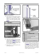
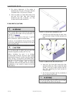
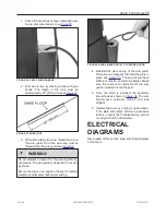
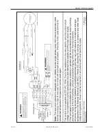
4. To reduce the lift up limit, turn by hand the up-
cam wheel counterclockwise looking from the
cam plate mounting screw side as shown in
. It has around 4° between each cam
wheel tooth and adding or removing a tooth
resolves in adding or removing approximately
5/32 in. (4 mm) on the cover lifting stroke.
FIGURE 81: CAM WHEELS
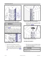
5. Once the up limit is set to the desired
position, reinstall the cam plate to its original
location and make sure that it is properly
inserted in the slot of each cam. Never
operate the system without the cam plate and
retaining screw installed.
6. Reinsert the slotted mounting screw.
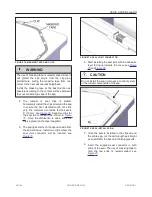
7. Reinstall the operator cover without screws.
8. Turn the power on and test the system.
Repeat the previous steps if necessary.
9. Once the adjustment is completed, fasten the
operator cover with the screws (4) .
241146
OWNER'S MANUAL
REVISION 1
Summary of Contents for OASIS COVER
Page 1: ......
Page 2: ......
Page 54: ......
Page 59: ...OASIS COVER page 57 241146 OWNER S MANUAL REVISION 1...
Page 61: ...OASIS COVER page 59 241146 OWNER S MANUAL REVISION 1...
Page 63: ...OASIS COVER page 61 241146 OWNER S MANUAL REVISION 1...
Page 65: ...OASIS COVER page 63 241146 OWNER S MANUAL REVISION 1...