


OASIS COVER page-
29
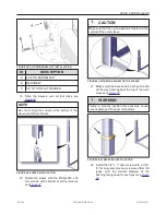
whereas the long- side model will need the
motor frame on the long side of the cover.
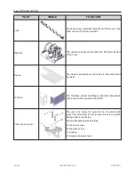
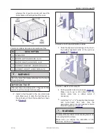
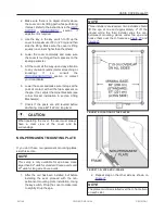
FIGURE 35: OPERATOR AND JACKS INSTALLATION
ID
DESCRIPTION
A
OPERATOR
B
MOTOR LEFT-HAND SIDE JACK
C
MOTOR RIGHT-HAND SIDE JACK
D
NON-MOTOR RIGHT-HAND SIDE JACK
E
NON-MOTOR LEFT-HAND SIDE JACK
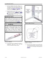
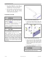
WARNING
Do not remove the alignment bracket on the top of
the jack (red part).
IMPORTANT NOTE
The next steps are side-specific. They are for the
non-motor left-hand side foot assembly.
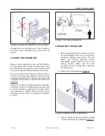
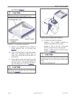
2. Install a foot bracket to the non-motor side
jack. Make sure to align the foot bracket on
the right side of the U-frame shaft as shown
see
.
FIGURE 36: FOOT BRACKET INSTALLATION
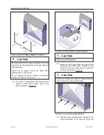
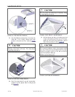
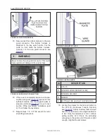
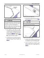
3. Slide the alignment vertical legs of the foot in
the bottom alignment slots of the jack see
and
FIGURE 37: INSERT LEGS IN SLOTS
4. Push upwards to lock in place see
.
Make sure to get a full contact with the
bottom
plate.
Use
a
rubber
mallet
if
necessary.
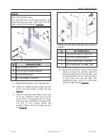
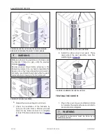
5. Install two 1/4″ x 2¼″ hexagonal head screws
and
nylon- insert
lock
nuts.
Use
the
appropriate socket wrench spanner to fasten
the foot in place see
.
WARNING
To prevent the mechanism from bending inward, do
not overtighten the screws.
Make sure you respect the orientation of the
fasteners, as shown in
.
241146
OWNER'S MANUAL
REVISION 1
Summary of Contents for OASIS COVER
Page 1: ......
Page 2: ......
Page 54: ......
Page 59: ...OASIS COVER page 57 241146 OWNER S MANUAL REVISION 1...
Page 61: ...OASIS COVER page 59 241146 OWNER S MANUAL REVISION 1...
Page 63: ...OASIS COVER page 61 241146 OWNER S MANUAL REVISION 1...
Page 65: ...OASIS COVER page 63 241146 OWNER S MANUAL REVISION 1...