


page-
34
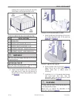
OASIS COVER
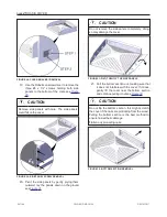
CAUTION
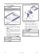
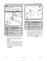
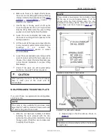
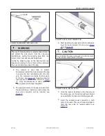
Make sure that the wider part of the bushing is
facing up when you screw in the 3/8″-24 x1″ Allen
bolt see
.
Ensure the hole in each top plate is aligned with the
jack assembly’s threads before installing the
screw see
.
FIGURE 49: FASTEN THE SLEEVE TO THE JACK
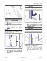
AC LIGHT KIT INSTALLATION
If the cover comes with a light kit, follow the steps
below. If not, skip to next section the Lifting
mechanism installation (part 2).
1. Before splitting the cover into two pieces,
fully unscrew any bolts on all four corners that
fasten the outer shell to the inner shell if
needed.
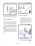
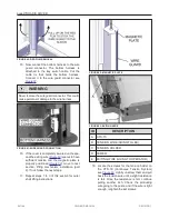
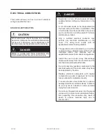
2. Locate the light switch button see
.
FIGURE 50: SHORT AND LONG SIDES OF THE COVER
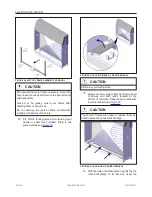
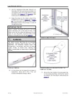
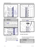
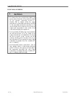
3. Lift and split the long side of the outer shell
opposite to the light switch button for the next
steps. To split the cover into two parts, you
must remove the outer shell by pushing
inwards on the steel frame of the inner shell
see
and
. This will clear
the metal inserts from the outer shell for better
leverage. Do not lift more than 16'' (40 cm).
NOTE
A non-abrasive or blunt tool may be used to help
hold the outer shell in place before moving to the
next steps.
CAUTION
Do not use any sharp or abrasive tools to hold the
outer shell in place while following the next steps.
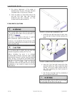
You should always hold the outer shell on the long
side at two different points spaced by about 34''
(85 cm )
WARNING
Do not lift the corners more than 16 in (40 cm),
further lifting may damage the outer shell.
Failure to follow this instruction will cause
permanent damage to the outer shell.
241146
OWNER'S MANUAL
REVISION 1
Summary of Contents for OASIS COVER
Page 1: ......
Page 2: ......
Page 54: ......
Page 59: ...OASIS COVER page 57 241146 OWNER S MANUAL REVISION 1...
Page 61: ...OASIS COVER page 59 241146 OWNER S MANUAL REVISION 1...
Page 63: ...OASIS COVER page 61 241146 OWNER S MANUAL REVISION 1...
Page 65: ...OASIS COVER page 63 241146 OWNER S MANUAL REVISION 1...