background image


21


ConteraIP Panoramic  |  Installation Manual  


7.  Using the screws provided (or other hardware), attach the Corner Mount Adapter to an exterior 90 

degree corner wall. 

8.  To attach the camera to the Wall Mount Adapter (AV-WMJB-W), reference the Installation and 

Wall Mount section. 

9.  To configure the camera, reference the camera discovery, set-up and configuration section. 


CAUTION!

 The captive screws must be used to properly secure the dome cover and camera housing. 

Failure to use the captive fastener may result in serious injury. When mounting the dome cover to the 
camera housing, ensure that the gasket is properly seated and not folded. Failure to do so may result in 
water and dust ingress. Water damage from improper installation is not covered by the warranty! 

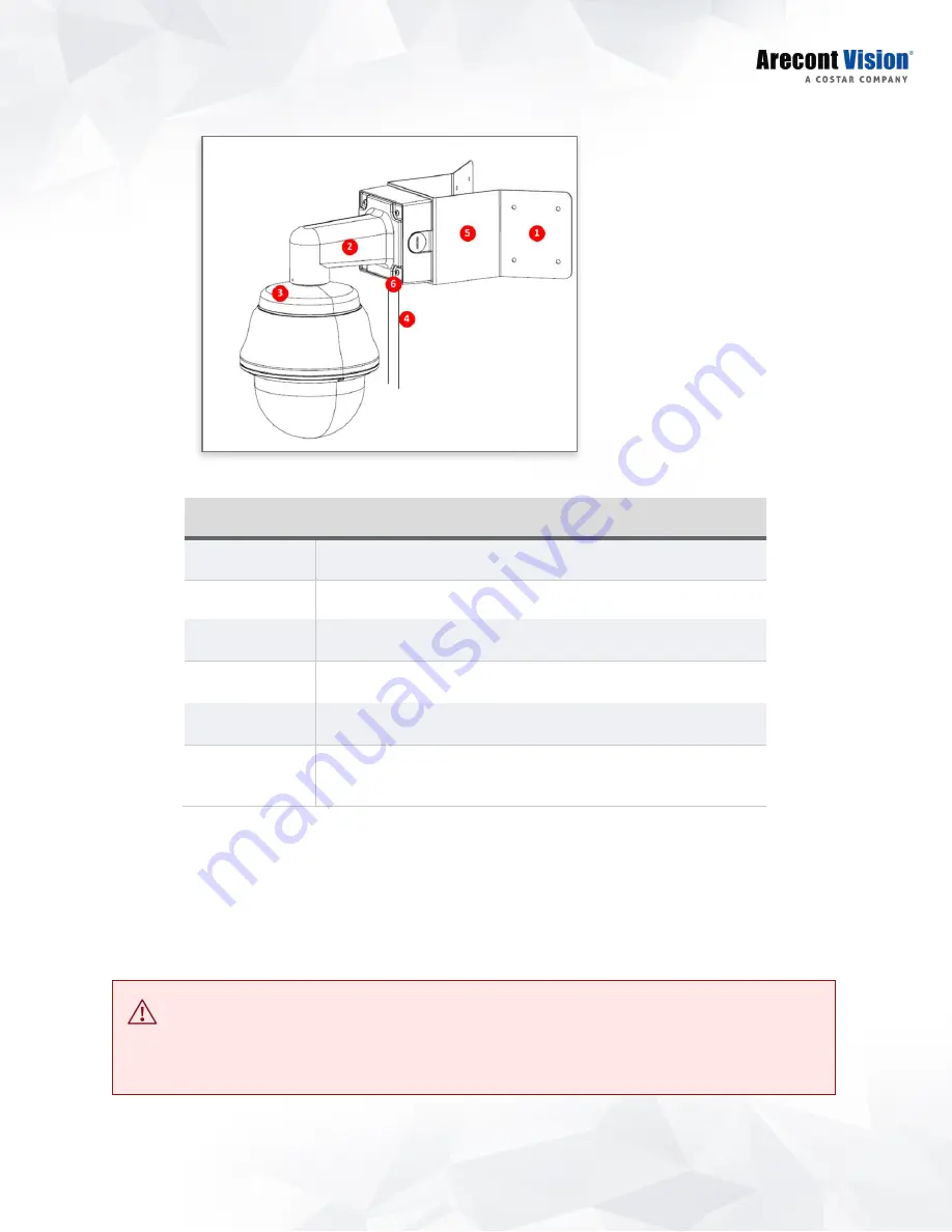
Reference # 

Description 

Attach corner mount adapter to exterior 90 corner wall 

AV-WMJB wall mount 

CP-CAP-W mount cap 

Conduit pipe 

AV-CRMA-W corner mount adapter 

Apply Teflon water seal tape to the thread of ¾” NPT pipe to 
avoid water leakage 

Summary of Contents for Arecont Vision AV08CPD-118

Page 1: ... 1 818 937 0700 www arecontvision com avsales arecontvision com ConteraIP Panoramic Installation Manual 8MP 20MP AV08CPD 118 AV20CPD 118 ...

Page 2: ...commendations 7 Surface Mount 9 Wall Mount 12 Pendant Mount 15 Pole Mount 18 Corner Mount 20 Electrical Box Adapter 22 Camera Power Up 23 Alarm I O Functions 24 Reset to Factory Default 24 Camera Discovery Setup and Configuration 25 Camera Discovery 25 Web Interface Navigation 26 Image 28 Video Audio 34 Network 37 Privacy Mask 41 Event 44 System 50 Administration 52 Support 54 ...

Page 3: ...ipment the Warranty Period b during the Warranty Period the Products will materially conform with the specification in the applicable documentation c all licensed programs accompanying the Product the Licensed Programs will materially conform with applicable specifications ARECONT VISION COSTAR warrants to Purchaser and only Purchaser the Limited Warranty that a each Product shall be free from mat...

Page 4: ...es the best visual balance to shaded and bright light conditions For clear color images in low light NightView offers strong low light sensitivity for capturing details in extremely poor lit scenes which is further enhanced by LED illumination built into each sensor gimbal Arecont Vision was the first to bring H 264 to the mainstream market and recently developed SNAPstream Smart Noise Adaptation ...

Page 5: ...with all local codes and authorities having jurisdiction Wiring should be UL Listed and or Recognized wire suitable for the application 3 Always use hardware e g screws anchors bolts locking nuts etc which are compatible with mounting surface and of sufficient length and construction to insure a secure mount Package Contents AV02CLB 100 AV05CLB 100 Cables Description QTY AV08CPD 118 AV20CPD 118 IP...

Page 6: ...6 ConteraIP Panoramic Installation Manual ...

Page 7: ...ounted from the ground toward the horizon For example a camera mounted at 30ft will have a 30ft blind spot below the camera and should be aimed 300ft toward the horizon In the example below the camera in Figures 1B and 1C are both mounted 30ft high however the camera in Figure 1B is aimed 250ft toward the horizon and the camera in Figure 1C is only aimed 150ft toward horizon As a result the camera...

Page 8: ...the camera in Figure 1D is aimed 80ft toward the horizon and the camera in Figure 1E is only aimed at 30ft toward horizon The camera in Figure 1E results in a drastic curvature with less usable video Figure 1D Mounting height of 8ft and aimed 80ft toward horizon Figure 1E Mounting height of 8ft and aimed only 30ft toward horizon ...

Page 9: ...t remove screws from the dome cover 3 After removing the dome cover loosen the four 4 screws and remove the bottom cover 4 Use the template anchors and screws provided to prepare the mounting provisions for the camera installation 5 Install four supplied dry wall anchors using the supplied mounting template 6 Align four supplied screws with the dry wall anchors and screw the back cover into place ...

Page 10: ...t the network cable to the camera s RJ45 connector 8 Install the main body with modules back into the back cover Fasten securely four 4 screws you l loosen from Step 3 NOTE Ensure the gasket between the back cover and the main body properly seated flush ...

Page 11: ... sides to fix the camera direction in place 12 Attach the dome cover back and fasten securely four captive screws CAUTION The captive screws must be used to properly secure the dome cover and camera housing Failure to use the captive fastener may result in serious injury When mounting the dome cover to the camera housing ensure that the gasket is properly seated and not folded Failure to do so may...

Page 12: ...isions for the camera installation 2 Connect wall mount cap and wall mount NOTE The thread size for Top shield pendant pole and mount is 1 5 NPT 3 Attach the wall mount to the wall using the four drywall screws provided or any optional hardware suitable for the mounting surface 4 Run the Ethernet cable and outside power cable if necessary through the wall mount Ensure the gasket is seated properly...

Page 13: ... 4 supplied screws 8 Connect the network cable to the camera s RJ45 connector 9 Install the main body with modules back into the back cover Fasten securely four 4 screws you loosen from Step 6 NOTE Ensure the gasket between the back cover and the main body properly seated flush 10 Loosen the manual easing gear and adjust the pan and tilt to obtain the desired field of view ...

Page 14: ...ttach the dome cover back and fasten securely four captive screws CAUTION The captive screws must be used to properly secure the dome cover and camera housing Failure to use the captive fastener may result in serious injury When mounting the dome cover to the camera housing ensure that the gasket is properly seated and not folded Failure to do so may result in water and dust ingress Water damage f...

Page 15: ...ons for the camera installation 2 Connect the cap pendant pole and mount together NOTE The thread size for Top shield pendant pole and mount is 1 5 NPT 3 Attach the pendant mount to the ceiling using the four wood screws provided or any optional hardware suitable for the mounting surface 4 Run the Ethernet cable and outside power cable if necessary through the Pendant mount Ensure the gasket is se...

Page 16: ... 4 supplied screws 8 Connect the network cable to the camera s RJ45 connector 9 Install the main body with modules back into the back cover Fasten securely four 4 screws you loosen from Step 6 NOTE Ensure the gasket between the back cover and the main body properly seated flush 10 Loosen the manual easing gear and adjust the pan and tilt to obtain the desired field of view ...

Page 17: ...ttach the dome cover back and fasten securely four captive screws CAUTION The captive screws must be used to properly secure the dome cover and camera housing Failure to use the captive fastener may result in serious injury When mounting the dome cover to the camera housing ensure that the gasket is properly seated and not folded Failure to do so may result in water and dust ingress Water damage f...

Page 18: ...t 3 Attach the Junction Box Adapter to the Pole Mount Adapter 4 Remove the conduit plug on the junction box adapter and connect NPT conduit to the junction box adapter NOTE Use silicon or water pipe seal tape to make sure no water leakage between conduit pipe and junction box adapter 5 Run the Ethernet cable and outside power cable if necessary through the Junction Box Adapter Ensure the gasket is...

Page 19: ...t be used to properly secure the dome cover and camera housing Failure to use the captive fastener may result in serious injury When mounting the dome cover to the camera housing ensure that the gasket is properly seated and not folded Failure to do so may result in water and dust ingress Water damage from improper installation is not covered by the warranty Reference Description 1 Steel straps wi...

Page 20: ... mount 3 Attach the Junction Box Adapter to the Corner Mount Adapter 4 Remove the conduit plug on the junction box adapter and connect NPT conduit to the junction box adapter NOTE Use silicon or water pipe seal tape to make sure no water leakage between conduit pipe and junction box adapter 5 Run the Ethernet cable and outside power cable if necessary through the Junction Box Adapter Ensure the ga...

Page 21: ...to properly secure the dome cover and camera housing Failure to use the captive fastener may result in serious injury When mounting the dome cover to the camera housing ensure that the gasket is properly seated and not folded Failure to do so may result in water and dust ingress Water damage from improper installation is not covered by the warranty Reference Description 1 Attach corner mount adapt...

Page 22: ...d sold separately 1 Attach the electrical box adapter to the user supplied electrical box 2 Using the supplied machine screws match the mounting holes 2 on the electrical box adapter with the holes on the camera back cover 3 Install the camera back cover on AV EBAS W 4 Install the main body with modules back into the back cover 5 Attach the dome cover back and fasten securely four captive screws ...

Page 23: ...ion CAUTION Make the connections inside a watertight compartment Isolate unused power wires individually After connections are made ensure that the watertight compartment is tightly closed and cables and conduits are properly sealed to prevent ingress of water 1 Connect the camera to a PoE port on 1000Mbps network PoE switch using an Ethernet cable 2 If the camera is powered by an outside power su...

Page 24: ...t Relay DC AC V sense V sense I sense V sense I sense 0 5V 0 220V 2A max 0 250V 2A max Reset to Factory Default 1 Press and hold the reset button for 2 to 5 seconds and release the reset button The camera has been reset to the factory default except the network settings 2 Press and hold the reset button for more than 5 seconds and release the reset button The camera has been reset to the factory 3...

Page 25: ...used for large installations that require an update to multiple settings or smaller installations where only one camera needs changed the AV IP Utility tool is efficient and convenient for mass or single camera uploads The AV IP Utility tool is compatible with all ConteraIPTM cameras The user manual for the software is included on the CD that came with your camera or available on our website Camer...

Page 26: ...on the top of the web interface Image Basic Image Settings WDR Wide Dynamic Range Settings IR Control OSD On Screen Display ROI Regions of Interest Video Audio Main Stream Configuration Sub Stream Configuration Third Stream Configuration Audio Network IP Assignment QoS Quality of Service UPnP Universal Plug and Play RTSP Real Time Streaming Protocol DDNS Dynamic DNS SNMP Simple Network Management ...

Page 27: ...System Firmware Upgrade Reboot Restore Settings Date Time Administration Administrator settings Viewer Management Support On the upper left corner you can find the Flip button that allows you to flip images 180 degree When you move the mouse over the top of each image channel you will see the channel number ...

Page 28: ...e brightness Sharpness Controls sharpness and edge definition of the image Setting this to lower levels may make overall image appear a bit softer while causing lines and edges in the image to look smoother Saturation Controls the color saturation of the image Contrast Manually controls Gamma level affects the overall luminance of the image Hue Configures the overall hue of the image the range is ...

Page 29: ...dual settings of the Exposure Time Control and Gain Control AWB Mode Auto White Balance Mode Auto Enables the automatic white balance feature of camera which will automatically remove unrealistic color cast so that white color is rendered white in the image Off Select Off to disable AWB Mode ...

Page 30: ...sure AE mode is set to Auto Turn off in low light Disables WDR backlight compensation when the light levels drop for better nighttime image quality Turn off in B W Disables WDR backlight compensation when the camera is in night mode for better nighttime image quality DWDR Digital WDR DWDR is to enhance dark areas by adjusting the gamma value This will not impact FPS of 20MP camera LDR Will not com...

Page 31: ...er exposure times reduces motion blur for applications such as monitoring fast moving objects and reading license plates The trade off is an increased level of noise It is recommended that this mode be used only when there is constant scene illumination sufficient to provide a quality image Lighting Compensation Frequency 50hz 60hz Custom Prevents flicker caused by the power line frequency of ligh...

Page 32: ...s are Translucent light grey or Transparent Text Color Options are Black White Green or Yellow Text Overlay Off Date Time Camera Name Camera Name Date Time Custom Text There are four content positions Top Left Top Right Bottom Left and Bottom Right to display the text overlay Date Time Displays the current date time It will force the camera to synchronize the date time information Camera Name Disp...

Page 33: ...her image quality while using lower image quality for other non ROI zones to save bandwidth and storage To setup the ROI 1 Select the desired channel 2 Select Main Stream or Sub Stream 3 Enable zones up to five zones and select the desired quality level High Medium or Low 4 Create the ROI by dragging the mouse over the live image 5 Press Save Area or Del Area ...

Page 34: ...t GOP and Smart ROI to reduce bitrate without impacting the image quality Smart GOP sets GOP to automatically increase when no moving objects are detected Smart ROI will increase the bitrate of moving objects and make them clearer Variable Bitrate Maintains the Quality setting configured There may be variation in the bit rate output from the camera using this mode Menu Feature Description Select c...

Page 35: ...up to 50 of specified FPS if WDR is enabled Note For 20MP models if one stream set to full resolution and another one set to full or half resolution the maximum FPS of the main and sub stream is up to 15 FPS GOP Length Specifies how many frames between two consecutive I Frames Video Compression MPJEG The third stream is designed for the live view on web interface and the only option of Video Compr...

Page 36: ...ned for the live view on web interface and the only option of Video Compression is MPJEG Audio In Audio Out Volume Encoding Enables the Audio In Audio Out features on the camera Specifies the volume level of Audio In Audio Out High Middle or Low Specifies the encoding algorithm A law or U Law ...

Page 37: ...rmine if a destination is from a different network Default Gateway Once set the camera will use send traffic to the specified gateway if the destination is on a different network Port HTTP Second HTTP Port HTTPs HTTP The port default is 80 It is used to access the camera via the web browser Second HTTP port Sets an alternative HTTP port This port can be useful when the standard HTTP port 80 is not...

Page 38: ...e for video traffic Management DSCP Sets DSCP value for non video traffic Enable UPnP Enables Universal Plug and Play function Select channel Select the desired channel to change RTSP settings Enable RTSP Unicast Stream Enables RTSP Unicast for stream 1 Main stream stream 2 Sub Stream and stream 3 Third Stream Enable RTSP Stream metadata Enables RTSP stream metadata for stream 1 Main stream stream...

Page 39: ...t address and the port number to stream audio This function is supported depends on models Meta IP Meta Port Configures the multicast address and the port number to the HTML meta Path Configures the URL address of the video stream TTL Configures the time to live threshold of the multicast datagram before it is discarded by the router Enable DDNS Enables DDNS service Host Name Specifies the Host na...

Page 40: ...g Specifies the destination IP address to send SNMP trap messages SNMP v3 Enables SNMP version 3 support SNMP User Specifies the user name of the SNMP v3 Authentication Password Selects one of the Authentication modes from the dropdown menu Options are None MD5 and SHA Specifies the Password for the Authentication Privacy Password Selects one of the encryption methods for SNMP v3 from the dropdown...

Page 41: ...ertificate Enable Enables FTP access to the camera Note This function is only available when a SD card is installed You can access files in the SD card via FTP Password Confirm Specifies and confirms the password to access the FTP Max Connection Specifies the maximum number of FTP connections to the IP camera Protocol The default is None to disable 802 1 x functions You can select one of the proto...

Page 42: ...tion Enable Privacy Mask Creates a privacy mask on the image so the selected areas will not be visible Select channel Select the desired channel to add privacy masks Drag mouse to Mask Unmask Select Mask to add privacy masks or Select Unmask to remove privacy masks ...

Page 43: ...e user to adjust vertical horizontal position of each channel Select channel Select the desired channel to change vertical horizontal position Vertical Horizontal Steps Select Down and Up to change image position vertically Select Left and Right to change image position horizontally Select the desired steps to do vertical horizontal alignment ...

Page 44: ...ber of which is set by the zone size setting up to 32x32 pixels This setting configures the sensitivity of the motion detection to the size of objects in the image moving through the zone Higher values will trigger motion only for larger objects moving through the zone lower values will cause detection of smaller objects in the zone increasing sensitivity to smaller size objects moving through the...

Page 45: ...lor indicates that the alarm schedule is disabled Alternatively you can manually enter numbers to configure the hours and minutes from start to end for all weekdays S Click S to set up a 24 hour schedule for a particular day D Click D to clear the previous schedule for a particular day Trigger Alarm Detection When a signal is detected from Alarm in the Alarm out will be triggered Trigger Motion De...

Page 46: ...s that the alarm schedule is disabled Alternatively you can manually enter numbers to configure the hours and minutes from start to end for all weekdays S Click S to set up a 24 hour schedule for a particular day D Click D to clear the previous schedule for a particular day Sensitivity Configures the sensitivity level of Tampering Detection High Medium and Low Enable Network Failure Enable network...

Page 47: ...larm Detection Trigger Motion Detection and Trigger Tampering Alarm SMTP Server Host Address Port Username Password Authentication Host Address Specifies the host name or IP address of the SMTP server Port Specifies the port number of the SMTP server Username Specifies the login username of the SMTP server Password Specifies the login password of the SMTP server Authentication Specifies the authen...

Page 48: ...ed or ok Network Address Specifies the IP address of the network storage server Folder Name Specifies the folder name on the network storage server Recoding Type Specifies the desired action when an event is triggered The options are Snapshot and Video Mount and Remove Network Storage Mount Sets up a network connection with the network storage server All the video recordings or snapshots from even...

Page 49: ...lable Storage Format SD Card Usage Status Overwrite when storage full Record Type Available Storage Displays the available storage of the SD card if it is installed Format SD Card Erases all the data stored on the SD Card Usage Displays the total storage that has been used now Status Displays the status whether the SD card is installed or not not_mounted or ok Overwrite when storage full Enables o...

Page 50: ...m Reboot the Camera Restore Factory Default Settings Except Network Settings Restore to Factory Default Settings Reboot the Camera Reboots the camera Restore Factory Default Settings Except Network Settings Restores all settings to factory default except the network settings Restore to Factory Default Settings Restores all settings to factory default Camera information Displays the information of ...

Page 51: ...t up appropriate gateway before configuring the NTP server Computer System Synchronizes the date time information with current computer s date time Once this option selected clicks Update Time from the computer Time Zone Specifies the country city of the time zone from the drop down menu NTP Server Specifies the desired NTP server ...

Page 52: ...e administrator Confirmation Re enters the password for the password validation Set Erase Saves or removes the password Note If admin password was set but has been lost it can be erased by AV IP Utility using the key file Please contact Arecont Vision technical support to obtain the key file required to perform this function Or if the camera has a reset button you can also reset to Factory default...

Page 53: ...me It must be at least five and up to sixteen characters User Viewer Password Specifies the password for the viewer Confirmation Re enters the password for the password validation Access Level Defines the authorization level for the user Admin or Viewer Set Erase Save or removes the password ...

Page 54: ...54 ConteraIP Panoramic Installation Manual Support Menu Feature Description Support Provides several useful hyperlinks to get more information of the camera ...

Page 55: ...ithout written permission from Arecont Vision The information in this publication is believed to be accurate in all respects However Arecont Vision cannot assume responsibility for any consequences resulting from the use thereof The information contained herein is subject to change without notice Revisions or new editions to this publication may be issued to incorporate such changes ...

Page 56: ...150 mm 150 mm ...

Reviews: