File : CS-SUP-MUTI-WTHERMAPP-E01.sxw
7.7.4 Triggering an alarm frame
After detection of a fault, if the configuration mode authorises transmission of alarms, the module transmits
an alarm frame (applicative command 0x40).
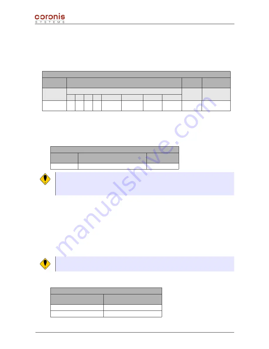
Structure of the alarm frame
Data Field (max : 152 bytes)
Applicative
Command
Alarm Status
Date
Data field
(optional)
1 byte
1 byte
b7
b6
b5
b4
b3
b2
b1
b0
6 bytes
variable
0x40
-
-
-
-
Probe
Fault
End of
battery life
High
Threshold
Low
Threshold
(1)
Bits of the Alarm Status :
0 :
not detected
1 :
detected
(1)
The data field is used when a threshold alarm is detected, its format is as follow :
Data field
Sensor
number
Duration
(in multiples of measurement period)
Integrated value
(*)
1 byte
2 bytes
(*) Integrated value :
average of all the values acquired since the first threshold detection, until its
disappearance. The size of this field depend on the type of the module used :
- WaveTherm – DALLAS :
2 bytes
- WaveTherm – PT100 :
4 bytes
- WaveTherm – PT1000 :
4 bytes
The remote device must send an acknowledgement frame (command 0xC0) to confirm reception of the
alarm frame and end dialogue.
If the WaveTherm module does not receive this acknowledgment, it re-transmits the alarm frame according
to the following parameters :
a set number of times, according to the value of the parameter 0x19
Between each re-transmission of a non-acknowledged alarm signal, the module waits for a
predefined time (configured by parameter 0x1A)
Attention, an alarm frame only has one type of detection. When several alarms are detected, the
WaveTherm module emits the frames one after the other.
An alarm frame will be transmitted after the previous frame has been acknowledged.
The recipient equipment have to acknowledge the alarm, with the following command :
Data Field (max : 152 bytes)
Acknowledgement of the
applicative command
Alarm status received in the
alarm frame
1 byte
1 byte
0xC0
WaveTherm modules – application handbook
page 63 of 65


