5 .3 Piston Rings and Piston Ring
Expander Replacement
Piston Ring Life—Dry Cylinder Compressor Applications
It is unrealistic to expect the same piston ring life from
a dry cylinder compressor as from a lubricated cylinder
machine because the PTFE rings have greater wear,
particularly under high temperature conditions.
CORKEN uses one of the best PTFE ring formulations
available. The normal life expectancy is approximately
2,200 hours of continuous service within recommended
compression ratios. However, ring life will vary considerably
depending upon piston speed (RPM), ambient temperature,
intermittent service conditions, compression ratio and the
nature of the gas being handled.
The secret to long ring life is operating at a low temperature.
A low ambient temperature and compression ratio along
with better intercooling will provide better ring wear.
Piston Ring Life—Lubricated Cylinder
Compressor Applications
If the compressor is equipped with cylinder lubrication,
piston rings have a longer service life than the dry
cylinder units described above.
Piston ring life varies considerably from application to
application but improves dramatically at lower speeds
and temperatures.
Piston and Piston Ring Expander Replacement
1. To replace the piston rings, depressurize the
compressor and purge if necessary.
2. Remove the cylinder cap (if any) and head.
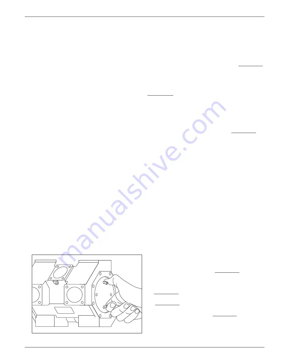
3. Loosen the piston cap screws and remove the piston
cap as shown in figure 5.3 by pinching two loose
screws together.
Figure 5.3
4. Remove the lock nut, washer and shims and pull the
piston off the end of the piston rod. Keep track of which
piston washer and shims came out of each cylinder.
5. Piston rings and expanders may then be easily
removed and replaced. Corken recommends replacing
expanders whenever rings are replaced. To determine
if rings should be replaced, measure the radial
thickness and compare it to the chart in Appendix B.
5 .4 Pistons
While reading the following instructions, refer to
Appendix D for parts details .
1. To replace the pistons, depressurize the compressor
and purge if necessary.
2. Remove the head (or adjusting screw nut, cylinder
cap, adjusting cup and head—applies to adjustable
head configuration only) as shown in Appendix D.
3. Remove the piston cap and shims by loosening and
removing the piston cap screws holding the piston cap
to the piston. Re-insert two loose screws as shown in
figure 5.3. Using fingers, pinch the screws together and
pull the piston cap out of the cylinder.
4. Remove the lock nut and thrust washer and pull the
piston out of the cylinder. Then, remove the thrust
washer and shims on the end of the piston rod.
5. Check the thrust washer and shims for damage and
replace if necessary.
6. Measure the thickness of the existing shims.
7. Insert one thrust washer against piston rod shoulder
followed by the same shims (or the same thickness of
shims) as before.
8. Before installing the piston, attach the piston ring
expanders and piston rings to the piston. Then, install
the piston on the piston rod.
9. Install a thrust washer and lock nut and tighten the
lock nut to the value listed in Appendix B.
10. Now remove an inboard valve and measure dimension
“Y” on the inboard end of the piston as shown in
Appendix B. If this measurement does not fall within
the tolerances listed in the piston assembly details
(Appendix B), remove the piston and adjust the shims
as necessary. Re-install the piston and tighten the
lock nut to the value listed in Appendix B. Re-measure
the “Y” dimension.
11. After the “Y” dimension is within tolerance, install
the piston cap with the same shim/shims (or same
thickness of shims) as before.
19


