NOTE: if the crankshaft roller bearings are too tight
or too loose, premature bearing failure will result.
10. Reinstall the flywheel and check the runout as shown
in Appendix B.
5 .8 Oil Pump Inspection
If the compressor operates for a prolonged period with
dirty or contaminated crankcase oil, damage to the oil
pump and bearings may result.
1. To check the oil pump, unbolt the oil filter adapter
and remove the oil pump, spring guide, spring and oil
pump shaft adapter as shown in figure 5.7B.
2. Inspect the gears in the oil pump for corrosion or
pitting and replace if necessary.
3. Check the oil pump shaft bushing in the bearing
carrier. If the bushing is corroded, pitted or worn, the
oil pump shaft bushing should be replaced. Inspect
and replace other parts as necessary.
4. Before reassembling the oil pump mechanism, replace
the O-rings in the oil filter adapter and on the oil pump
shaft adapter (see figure 5.7B).
5. Rotate the drive pin in the crankshaft to a vertical
position for easiest reassembly.
6. Insert the pump shaft adapter so it engages the drive pin.
7. Next, insert the spring, spring guide and oil pump
assembly. The pin on the oil pump must align with the
slot in the oil pump shaft adapter.
8. As the oil filter adapter is attached to the bearing carrier,
make certain the pin on the back of the oil filter adapter
aligns with the opening on the oil pump assembly as
shown in figure 5.7B. When the pin is properly aligned,
install the oil filter adapter bolts finger tight. If alignment
is correct, the oil filter adapter will mount flush to the
bearing carrier. If it does not, re-check the pin alignment.
9. Tighten the bolts in an alternating sequence. See
section 3.3 for directions on oil pressure adjustment.
10.
Finally, rotate the crankshaft by hand to ensure
smooth operation. Then rotate it in opposite directions,
listening for a click, which indicates proper alignment
of the oil pump’s pins and slots.
5 .9 Disposal
Disposal of compressor or components (once deemed
non-usable by the factory and end user) should be done
in accordance with all applicable codes. Contact the
local waste management authorities to determine proper
disposal methods.
Chapter 6—Extended Storage
Procedures
Following a few simple procedures will greatly minimize
the risk of the unit becoming corroded and damaged.
Corken recommends the following precautions to protect
the compressor during storage:
1. Drain the crankcase oil and refill with rust inhibiting oil.
2. Operate for a few minutes while fogging oil into the
compressor suction.
3. Relieve V-belt tension.
4. Plug all openings to prevent entry of insects and
moisture. (The cylinders may also be protected by the
use of a vapor phase inhibitor, silica gel, or dry nitrogen
gas. If the silica gel is used, hang a tag on the unit
indicating that it must be removed before startup.)
5. Store in a dry area and off the ground if possible.
6. Rotate the flywheel every two weeks if possible.
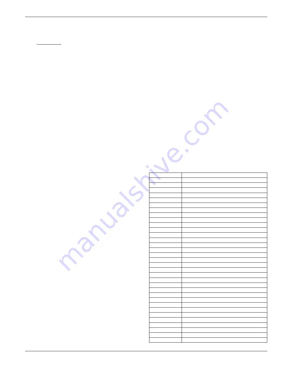
6 .1 Repair Kits
Repair Kit
Part Type
3788-X1
Crankcase
3792-X1A
8" cylinder Buna-N
3792-X1D
8" cylinder Viton
®1
3792-X1E
8" cylinder PTFE
3792-X2A
8" cylinder Buna-N
3792-X2E
8" cylinder PTFE
3792-X3E
8" cylinder PTFE
3791-X1A
6" cylinder Buna-N
3791-X1D
6" cylinder Viton
®1
3791-X1E
6" cylinder PTFE
3791-X2A
6" cylinder Buna-N
3791-X2D
6" cylinder Viton
®1
3791-X2E
6" cylinder PTFE
3792-X3E
6" cylinder PTFE
5335-X1A
5" cylinder Buna-N
5335-X1D
5" cylinder Viton
®1
5335-X1E
5" cylinder PTFE
3790-X1A
4" cylinder Buna-N
3790-X1D
4" cylinder Viton
®1
3790-X1E
4" cylinder PTFE
3790-X3E
4" cylinder PTFE
3789-X1A
3-1/4" cylinder Buna-N
3789-X1D
3-1/4" cylinder Viton
®1
3789-X1E
3-1/4" cylinder PTFE
3789-X2A
3-1/4" cylinder Buna-N
3789-X2D
3-1/4" cylinder Viton
®1
3789-X2E
3-1/4" cylinder PTFE
3789-X3E
3-1/4" cylinder PTFE
3950-X1A
2-3/4" cylinder Buna-N
3950-X1E
2-3/4" cylinder PTFE
3950-X3A
2-3/4" cylinder Buna-N
3950-X3D
2-3/4" cylinder Viton
®1
3950-X3E
2-3/4" cylinder PTFE
1
Registered trademark of the DuPont company.
29


