background image

If the compressor is equipped with a liquid trap not 
manufactured by Corken, make sure it is adequately 
sized; otherwise, it may not be able to remove the liquid 
entrained in the suction stream.

Corken’s liquid trap provides the most thorough liquid 
separation (see figure 1.4) and is American Society of 
Mechanical Engineers (ASME) code stamped. It contains:

• Manual drain valve. 

• Relief valve designed according to the ASME code to 

protect the vessel

• Pressure gauge with isolation needle valve

• Two (2) level switches: one for alarm and one for 

shutdown. In some cases, the alarm switch is used to 
activate a dump valve (not included with trap) or sound 
an alarm so the operator can drain the trap using the 
manual drain valve at the bottom of the trap. 

• This trap also contains a mist pad. A mist pad is a mesh 

of interwoven wire designed to remove fine liquid mists.

NOTE: The liquid level switches MUST be removed 
from the trap before grounding any welding devices 
to the trap or associated piping . Failure to do so will 
damage the switch contacts!

2 .5 Driver Installation and Flywheels

Corken compressors may be driven by either electric 
motors or internal combustion engines (e.g. gasoline, 
diesel, natural gas, etc.). They are usually V-belt driven. 
The fly wheel has dual purpose it is sheave for the 
V-belts and for compressor speed variation reduction.

The electric motor wiring is extremely important and 
must be done by a competent electrician. Low voltage 
or improper wiring of the motor will result in expensive 
consequences. If there is a low voltage problem, call the 
power company. 

Humid climates can cause problems with explosion 
proof motors. Explosion proof and TEFC motors are 
designed to expand and contract due temperature 
changes. This allows air to enter and exit the enclosures. 
The moist air inside the motor can condense and if 
enough water accumulates, the motor will fail. 

To prevent this two method can be followed

• Make a practice of running the motor at least once 

a week on a bright, dry day for an hour. During this 
period of time, the motor will heat up and vaporize the 
condensed moisture.

• Motor space heaters are recommended which need to 

be powered at all times to vaporize the any moisture.

NOTE: No motor manufacturer will guarantee their 
explosion proof or totally enclosed (TEFC) motor 
against damage from moisture .

Drivers should be selected so the compressor operates 
between 400 and 1200 RPM. The unit must not 
be operated without the flywheel or severe torsional 
imbalances will result causing vibration and a high 
horsepower requirement. The flywheel should never 
be replaced unless it has a higher wk2 value than the 
flywheel supplied from factory.

For installation with engine drivers, thoroughly review 
instructions from the engine manufacturer to assure the 
unit is properly installed.

2 .6 Crankcase Lubrication

The crankcase was drained before shipment. Before 
starting the machine, fill the crankcase to the full mark 
on the oil bayonet and not above. To ensure proper 
lubrication of the crankcase parts, the crankcase should 
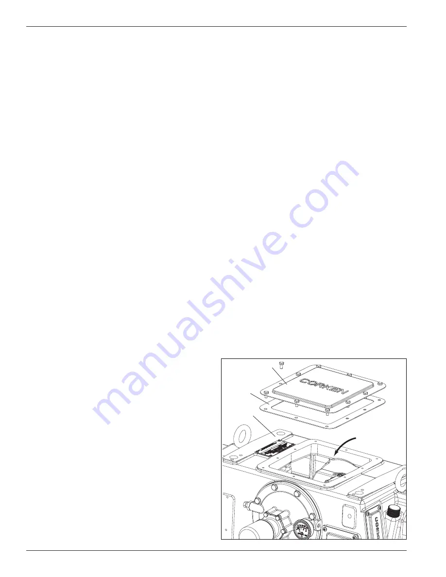
be filled through the crankcase inspection plate (see 
figure 2.6A for the proper oil filling location).

General Notes on Crankcase Oil

Corken gas compressors handle a wide variety of 
gases in a multitude of operating conditions. They 
are used in all areas of the world from hot dusty 
deserts, to humid coastal areas, to cold arctic climates. 
Some compressors may be lightly loaded and run 
only occasionally, while others may be heavily loaded 
and operate 24/7. Thus, no single crankcase oil or 
maintenance schedule is right for every compressor. 
Availability of brands and grades of oil can vary from 
one location to another. These factors can make it 

Figure 2.6A

Inspection plate

Inspection plate

gasket

Crankcase

Fill crankcase

through this opening

8

Summary of Contents for HG601 Series

Page 1: ...ducts must be made only by experienced trained and qualified personnel 3 Maintenance use and installation of Corken products must comply with Corken instructions applicable laws and safety standards 4...

Page 2: ...nties including any implied warranty of merchantability or fitness for a particular purpose are expressly negated to the extent permitted by law and shall in no event extend beyond the expressed warra...

Page 3: ...Lubrication Lubed models only 15 3 7 Variable Clearance Heads VCH 16 3 8 Startup Check List 16 Chapter 4 Routine Maintenance Chart 17 Chapter 5 Routine Service and Repair Procedures 17 5 1 Compressor...

Page 4: ...zed gas in the compression chamber from the crankcase While piston rings seal the piston tightly enough for it to do compression work they do not provide enough sealing to isolate the compression cham...

Page 5: ...ner oil wiper ring set Inner packing set Heavy duty crankcase A rugged internally ribbed design incorporating heavy duty main bearings and four bolt connecting rods Variable clearance head Allows chan...

Page 6: ...SUPPORT PIPING WITH THE COMPRESSOR The compressor must not support any significant piping weight therefore the piping must be fully supported The use of flexible connections to the compressor is highl...

Page 7: ...ce In the United States the following codes apply For LP Gas The National Fire Protection Association Pamphlet No 58 Standard for the Storage and Handling of Liquefied Petroleum Gases For Ammonia The...

Page 8: ...ide the motor can condense and if enough water accumulates the motor will fail To prevent this two method can be followed Make a practice of running the motor at least once a week on a bright dry day...

Page 9: ...e unable to protect the components from wear Viscosity Index Viscosity Index VI is a measure of how much the oil s viscosity changes as its temperature changes A low viscosity index is an indication t...

Page 10: ...e 2 Viscosity ISO 3 Viscosity Index3 Pour Point 3 40 to 100 F 4 to 38 C Mobil DTE 10 Excel 100 C 100 127 27 F 33 C Mobil Rarus 427 C 100 100 16 F 9 C Phillips 66 Gas Compressor Oil C 100 102 20 F 29 C...

Page 11: ...3suchtests adetermination can be made for a recommended oil change interval for a particular compressor in its specific environmental situation and operating conditions Regular oil analysis can help i...

Page 12: ...o select the set pressure on a relief valve located on compressor piping discharge is for it to be between 10 20 above the highest discharge pressure the compressor can produce but less than the maxim...

Page 13: ...lywheel and V belt Alignment Before working on the drive assembly be sure that the electric power is disconnected When mounting new belts always make sure the driver and compressor are close enough to...

Page 14: ...gauge If the gauge fails to indicate pressure within 30 seconds stop the machine and loosen the oil filter Restart the compressor and run until oil comes out and tighten the filter The oil pressure s...

Page 15: ...end of the crankcase see lubricator assembly details in Appendix D Since lubricators supplied with Corken compressors are made by a number of different manufacturers refer to the manufacturer s instr...

Page 16: ...ipated conditions 3 Ensure that line pressures are within cylinder pressure ratings 4 Clean out all piping 5 Check all mounting shims cylinder and piping supports to ensure that no undue twisting forc...

Page 17: ...part details appendix in the back of this Installation Operation Maintenance IOM manual for a complete list of part numbers and descriptions 5 1 Compressor Valves Test the compressor valves by closin...

Page 18: ...valves may simply be cleaned and reinstalled If the valves show any damage they should be repaired or replaced Replacement is usually preferable although repair parts are available If valve plates are...

Page 19: ...ed Corken recommends replacing expanders whenever rings are replaced To determine if rings should be replaced measure the radial thickness and compare it to the chart in Appendix B 5 4 Pistons While r...

Page 20: ...to smooth the cylinder bore and then polish it to the value shown in Appendix B If more than 005 of an inch must be removed to smooth the bore replace the cylinder Cylinder liners and oversized rings...

Page 21: ...the packing cartridge cap to the adapter It is not normally necessary to remove the adapter from the crankcase in order to disassemble or reassemble the packing c Partially insert the bolts in the pu...

Page 22: ...re is needed to keep from losing them or having them become dislodged during assembly d Install a purge packing cup with O ring and biased packing set tangent tangent with springs toward crankcase sTT...

Page 23: ...Pull outward to remove the packing cartridge assembly from the adapter and over the piston rod a 2 3 4 and 3 1 4 Cylinders Using a pair of flat bladed screwdrivers or similar tools engage the annular...

Page 24: ...mbly Place the oil wiper ring cup and oil wiper ring set onto the purge packing cup A full inner packing set is now positioned on the end plate of the tool See figure 5 6C c Orient the packing cartrid...

Page 25: ...plate Nut Slotted clamp Purge packing cup and inner packing set Packing assembly tool 4794 X Step 2 Figure 5 6D Packing assembly Cup spacer Socket head screw Packing cartridge adapter Packing cartrid...

Page 26: ...ause most packing cartridge bodies can only be installed in one position i Install the packing cartridge cap in the adapter Be sure the mark previously made on the packing cartridge cap is oriented up...

Page 27: ...rankshaft throw and bearing surface are clean and lubricated Tighten the connecting rod nuts to the torque value listed in Appendix B 5 7 3 Replacing Crankcase Roller Bearings To inspect the roller be...

Page 28: ...ring cup and bearing cover Slowly lower the opposite end of the crankshaft to the bottom of the bearing carrier opening 6 Before installing the bearing carrier make sure the slot at the end of the oil...

Page 29: ...proper alignment of the oil pump s pins and slots 5 9 Disposal Disposal of compressor or components once deemed non usable by the factory and end user should be done in accordance with all applicable...

Page 30: ...Standard head PTFE steel 3582 X2A 3 1 4 Adjustable head Buna N steel 3582 X2D 3 1 4 Adjustable head Viton 1 steel 3582 X2E 3 1 4 Adjustable head PTFE steel 3582 X2B 3 1 4 Adjustable head Neoprene 1 s...

Page 31: ...all areas accessible to personnel which contain concentrations of process gases capable of displacing breathing air shall be kept at acceptable levels per all local regulations codes 6 End user to tak...

Page 32: ...a hoist forklift or sling to the lifting eye s on the crankcase of the compressor End user must ensure the lifting apparatus has a load capacity at least as large as the weight of the compressor bein...

Page 33: ...33...

Page 34: ...l NA NA NA NA NA 4BL1 Low inlet pressure valves and blank valves with PEEK plates NA Optional NA NA NA NA 4PBL1 Unloaders Optional NA NA Optional Optional NA 9 Unloaders with PEEK plates NA Optional O...

Page 35: ...ves with blank valves Optional NA NA NA NA NA 4BL1 Low inlet pressure valves and blank valves with PEEK plates NA Optional NA NA NA NA 4PBL1 Unloaders Optional NA NA Optional Optional NA 9 Unloaders w...

Page 36: ...age with PEEK plates Optional Optional NA Optional Optional 4PFL1 Standard valves with blank valves in 2nd stage NA NA Optional NA NA 4S Standard and blank valves in 2nd stage with PEEK plates Optiona...

Page 37: ...ous page Piston Ring and Packing Material PTFE piston and Alloy 50 packing material Standard F Gasket Material Steel Standard D O ring Material Buna N Standard A Neoprene 2 No charge option B Viton 2...

Page 38: ...dard valves w blank valves in 2nd stage w PEEK plates Optional 4PS Low inlet pressure valves with blank valves in 2nd stage with PEEK plates Optional Optional NA NA NA 4PSL1 Unloaders with PEEK plates...

Page 39: ...1st stage Optional 4F Standard valves with blank valves in 2nd stage Optional 4S Unloaders Optional NA 9 Unloaders with blank valves in both stages Optional NA 9B Unloaders with blank valves in 1st s...

Page 40: ...andard NA 4 Standard valves with PEEK plates NA Standard NA Standard 4P Suction valve unloaders Optional NA Optional NA 9 Suction valve unloaders with PEEK plates NA Optional NA Optional 9P Piston Rin...

Page 41: ...Data Stroke inches mm 3 0 76 2 Maximum gas rod load lb kg 7 500 3 401 9 Maximum motor size hp kg 75 55 9 Maximum discharge temp F C 1 350 6 177 Minimum temp F C 1 20 28 9 RPM range 400 1 200 THG HG600...

Page 42: ...7 870 394 6 845 383 3 845 383 3 THG model 1 170 530 7 1 010 458 1 990 449 1 970 440 0 945 428 7 945 428 7 Two stage Horizontal Compressors Two Cylinder Models HG602AB THG602AB HG602AC THG602AC HG602AD...

Page 43: ...1EE 429 HG601FF 383 THG601FF 429 HG602AB 449 THG602AB 494 HG602AC 444 THG602AC 490 Horizontal Compressor Model Machine Mass kg Horizontal Compressor Model Machine Mass kg HG602AD 440 THG602AD 485 HG60...

Page 44: ...25 4 5 Steel 6 8 Aluminum A356 T6 Ductile iron A536 Grade 65 45 12 single stage only Piston rod All 1045 Steel Nitrotec 1 Crosshead All Gray iron ASTM A48 Class 30 Connecting rod and packing cartridge...

Page 45: ...ylinder to adapter 1 65 65 65 65 65 65 Valve cover plate bolt 35 35 40 40 40 40 Valve holddown screw2 40 40 40 40 40 40 Piston nut torque 150 150 150 150 150 150 Piston screw torque 100 50 100 100 100...

Page 46: ...93 2 36 0 093 2 36 0 098 2 49 T Style Bottom minimum clearance Y 0 005 0 13 0 005 0 13 0 005 0 13 0 005 0 13 0 005 0 13 0 005 0 13 Bottom maximum clearance Y 0 015 0 38 0 015 0 38 0 015 0 38 0 015 0 3...

Page 47: ...863 9 2 slip on 6 22 94 582 7 5 94 150 9 30 25 768 4 33 06 839 7 2 slip on 8 23 63 600 2 7 25 184 2 32 13 816 1 34 69 881 1 3 slip on a 1 5 Class 1500 RF flange not supplied NOTE 1 Standard flywheel...

Page 48: ...25 184 2 32 13 816 1 34 69 881 1 3 slip on a 1 5 Class 1500 RF flange not supplied NOTE 1 Standard flywheel not shown 5 5V 21 2 2 Jacking screw provided for cylinder support 8 and 6 cylinders only In...

Page 49: ...1 062 2 2 slip on 6 30 75 781 1 5 94 150 9 38 07 967 0 40 88 1 038 4 2 slip on 8 31 50 800 1 7 25 184 2 40 07 1 017 8 42 88 1 089 0 3 slip on a 1 5 Class 1500 RF flange not supplied NOTE 1 Standard fl...

Page 50: ...slip on 8 31 50 800 1 7 25 184 2 40 07 1 017 8 42 88 1 089 0 3 slip on a 1 5 Class 1500 RF flange not supplied NOTE 1 Standard flywheel not shown 5 5V 21 2 2 Jacking screw provided for cylinder suppor...

Page 51: ...pressure in the unit before attempting any repairs Cylinder Bill of Materials Ref No Part No Description Qty per Cylinder 1 2 232_a O ring 2 2 3888 Cylinder 1 3 3899 1 Adjustable head 1 4 2 225_ a f...

Page 52: ...3665 3665 Adjusting screw nut 1 13 7001 050NC150A 7001 050NC150A 7001 050NC150A Bolt hex head 1 2 13 x 1 1 2 16 14 3527 3763 5293 Head 1 15 3442 3442 3442 Pipe plug 1 4 4 16 3698 3698 3698 Nameplate...

Page 53: ...3663 3683 Adjusting cup 1 9 2 250_ a 2 262_ a O ring 1 10 3637 3682 Adjusting cap 1 11 2 127_ a 2 127_ a O ring 1 12 3665 3665 Adjusting screw nut 1 13 7001 050NC150A 7001 050NC150A Bolt hex head 1 2...

Page 54: ...01 043NC150A 16 2 Valve cover plate 3894 4 2205 4 1764 4 3 O ring 2 224_ b 4 2 143_ b 4 2 235_ b 4 4 Suction valve assembly 3900 X steel 2 4029 X2 steel 2 3807 X steel 2 5 Discharge valve assembly 390...

Page 55: ...y 3857 5X2 steel 2 3857 2X2 steel 4 3709 X2 steel 4 6 Valve gasket 2114a 4 2114a 4 3691 a 4 7 Valve cap 2714 1d 4 2714 1d 4 2714 1d 4 8 O ring 2 031_ b 4 2 031_ b 4 2 031_ b 4 9 Holddown screw 2715 4...

Page 56: ...r 3939 4 3826 4 3857 4 8 Spring buttona 9 Spring inner a 3924 4 3829 4 3929 4 3829 1 Inconel optional Spring outer a 3928 4 10 Repair kit 3804 X1 4 3124 X suction 2 3805 X1 4 3146 X1 4 3125 X discharg...

Page 57: ...3709 X aluminum 4 3709 X aluminum 4 3857 5X2 steel 4 3857 3X2 steel 4 3709 X2 steel 4 3709 X2 steel 4 3 Valve seat 3856 4 3856 4 3834 2 3834 2 4 Stud c 3920 4 3920 4 3828 2 3828 2 5 Valve plate inner...

Page 58: ...1 NOTE See Appendix B for piston clearance specifications 1 2 3 4 6 2 7 8 9 10 Piston rod see connecting rod assembly for more information 7 11 8 Piston Size NOTE See Appendix B for piston clearance s...

Page 59: ...b 3812 1 3812 1 3812 1 Ref No Description Cylinder Diameter 5 6 8 Part No Qty Part No Qty Part No Qty 1 Piston assembly iron 5301 X1 3530 X1 1 3674 X1 1 Piston assembly aluminum 5301 1X1 1 3530 1X1 1...

Page 60: ...c Direction of oil wiper ring set is important See packing assembly page for details d _ denotes material code See material code chart for details e Registered trademark of the DuPont company f Apply...

Page 61: ...g location b Direction of packing is important See packing assembly page for details c Direction of oil wiper ring set is important See packing assembly page for details d _ denotes material code See...

Page 62: ...etails c Direction of oil wiper ring set is important See packing assembly page for details d _ denotes material code See material code chart for details e Registered trademark of the DuPont company f...

Page 63: ...4 1 a See detail for O ring location b Direction of packing is important See packing assembly page for details c Direction of oil wiper ring set is important See packing assembly page for details d _...

Page 64: ...mbly page for details d _ denotes material code See material code chart for details e Registered trademark of the DuPont company f Apply a small amount of Loctite 272 to the circumference of the threa...

Page 65: ...is important See packing assembly page for details c Direction of oil wiper ring set is important See packing assembly page for details d _ denotes material code See material code chart for details e...

Page 66: ...cking assembly page for details d _ denotes material code See material code chart for details e Registered trademark of the DuPont company f Apply a small amount of Loctite 272 to the circumference of...

Page 67: ...b Direction of packing is important See packing assembly page for details c Direction of oil wiper ring set is important See packing assembly page for details d _ denotes material code See material co...

Page 68: ...ded Cup Spacer not included Backup Ring with 6 springs Crankcase Side Cylinder Side 1 Standard Specification Oil wiper ring set Radial Radial 2 Purge Specification Oil wiper ring set Radial Radial Par...

Page 69: ...ng not included Crankcase Side Cylinder Side Packing Cup not included Backup Ring not included Align pin with hole on backside Tangent Cut with pin Tangent Cut without pin Crankcase Side Cylinder Side...

Page 70: ...ing set 1 a See detail for O ring location b Direction of packing is important See packing assembly page for details c Direction of oil wiper ring set is important See packing assembly page for detail...

Page 71: ...of packing is important See packing assembly page for details c Direction of oil wiper ring set is important See packing assembly page for details d _ denotes material code See material code chart for...

Page 72: ...4 27 4273 1X2 Packing set 1 a See detail for O ring location b Direction of packing is important See packing assembly page for details c Direction of oil wiper ring set is important See packing assemb...

Page 73: ...ee detail for O ring location b Direction of packing is important See packing assembly page for details c Direction of oil wiper ring set is important See packing assembly page for details d _ denotes...

Page 74: ...egmented Packing Set Tangent Tangent with springs toward cylinder TTs Part number 3816 Part number 4273 Middle Packing Details Backup Ring not included Packing Cup not included Align pin with hole on...

Page 75: ...ncluded Purge Packing Spacer not included Crankcase Side Cylinder Side Packing Cup not included Breaker Ring Crankcase Side Cylinder Side 1 Pad Specification Segmented Packing Set Tangent Tangent 2 Pa...

Page 76: ...t 4 3 3542 Connecting rod bearing pair 1 4 1726 Connecting rod bolt 4 5 3541 a Wrist pin bushing 1 6 3590 Wrist pin retainer ring 2 7 3544 X1 Crosshead assembly HG600 1 3544 X11 Crosshead assembly THG...

Page 77: ...043NC150A a Bolt hex head 1 2 13 x 1 1 2 8 8 8 8 8 8 8 8 6 7001 050NC250A b Bolt hex head 7 16 14 x 2 1 2 3 3 3 3 9 7 3812 Loctite 620 tube 1 1 1 1 1 1 1 1 a Use Loctite retaining compound 620 and tor...

Page 78: ...ather cap and ball details 31 34 34 32 32 35 29 33 33 Note Oil transfer tubing mounts inside the crankcase 4 3 2 5 Cross section of bearing carrier shows lubrication tubing used to lubricate the cross...

Page 79: ...1435 Tee 1 8 P x 1 4 T x 1 4 T brass 2 34 1399 Male elbow 1 8 P x 1 4 T brass 2 35 3643 Pipe plug 1 NPT steel 1 Crankcase Assembly Bill of Materials Ref No Part No Description Qty 1 3538 Crankcase 1 3...

Page 80: ...s Ref No Part No Description Qty 14 2 112A O ring 1 15 3219 Pump shaft adapter 1 16 2852 Oil pump spring 1 17 2851 Spring guide 1 18 2849 1X a Oil pump assembly 1 19 2 228A O ring 1 20 4222 Oil filter...

Page 81: ...C100A Bolt hex head 3 8 16 x 1 4 16 3526 Oil seal 1 a Caution To avoid damage during assembly refer to Important Instructions IE400 Crankcase Assembly Bill of Materials Ref No Part No Description Qty...

Page 82: ...k check valve 2 26 3668 Xc Divider valve assembly single cylinder 1 27 7201 037A Washer 3 8 4 a Except 2 3 4 cylinder b 2 3 4 cylinder only c Single cylinder units only d Optional Crankcase Assembly B...

Page 83: ...e plug 1 8 NPT flush 1 a Must be installed in the center hole on the backside of the oil filter adapter See reference 29 on page 80 for details on the backside of the oil filter adapter part 4222 Ref...

Page 84: ...2 2 2 2 2 2 Back Side Front Side Flywheel Bill of Materials Ref No Part No Description Qty 1 3852 Flywheel 21 2 O D 5 V grooves 1 2 H J 2 125 Hub with three bolts and lockwashers 1 Assembly Number Ass...

Page 85: ...8 14 Oil leakage around compressor base 16 17 No oil pressure 18 19 Excessive vibration 1 7 9 10 11 12 13 25 27 Motor overheating or starter tripping out 20 21 22 23 24 25 26 27 Ref No Possible Causes...

Page 86: ...ristics Voltage phase and frequency must coincide with motor nameplate Consult with power company 24 Wrong size of heaters in starter Check and replace according to manufacturer s instructions 25 Comp...

Page 87: ......

Page 88: ...h 2020 CORKEN INC A Unit of IDEX Corporation 9201 North I 35 Service Road Oklahoma City OK 73131 Phone 405 946 5576 Fax 405 948 7343 Website www corken com E mail cocsalesdept idexcorp com Solutions b...

Reviews: