background image

18

18

19

19

20

20

21

11

2

11

12
13

14

21

21

21

22

22

13

12

15

16

17

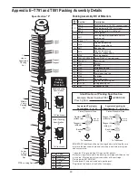
Packing barrels 

and cartridges

(For parts details, 

see T891 packing 

on previous pages).

Ref 
No.

Part No.

Description

Qty

1.

3922

Cylinder

1

2.

3442

Pipe plug (1/4" NPT)

12

3.

1054

Drain valve (lubricated models)

1

4.

1071

Nipple (1/4" x close)

1

5.

2-246_a

O-ring for cylinder

2

6.

7001-050NC175A

Bolt (1/2" 13 x 1-3/4" hex head 
gr 5)

6

7.

3793-2S

Flange (inlet/outlet)

2

8.

2-231_a

O-ring for flange

2

9.

3253

Roll pin

1

10. 1716-4

Crosshead guide

1

11. 7005-050175A

Bolt (1/2" 13 x 1-3/4" ferry head)

16

12. 1748

Cartridge plate

2

13. 5000-350

Retainer ring

2

14. 1761

Gasket (crankcase)

1

15. 1760

Gasket (inspection cover)

1

16. 1721

Inspection cover

1

17.

7012-010NC025B Bolt (10 - 24 x 1/4" Phillips hd.)

10

18. 2-238_a

O-ring

2

19. 1749

Cartridge holddown screw

2

20. 4747

Cage

2

21. 2-233_a

O-ring

2

22. 1732

Oil deflector ring

2

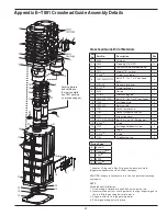
Crosshead Guide Bill of Materials

Appendix E—T891 Crosshead Guide Assembly Details

_ denotes O-ring code. See O-ring chart above for details.

Registered trademark of the DuPont company.

CAUTION: Always relieve pressure in the unit before attempting 
any repairs.

NOTE:  


Packing barrel installation: 


1.  Use packing installation cone #3905 on the piston rod.
2.  Insert small barrel first, use finger holes to align slinger ring on to 

the rod. Slip the packing barrel into place.

3.  Align pin with slot in large packing barrel.
4.  Slip large packing barrel in place.

O-ring Code

A

Buna-N

B

Neoprene

®b

D

Viton

®b

E

PTFE

K

Kalrez

®b

47

Summary of Contents for D791

Page 1: ...orken products must be made only by experienced trained and qualified personnel 3 Maintenance use and installation of Corken products must comply with Corken instructions applicable laws and safety standards such as NFPA Pamphlet 58 for LP Gas and ANSI K61 1 1972 for Anhydrous Ammonia 4 Transfer of toxic dangerous flammable or explosive substances using Corken products is at user s risk and equipm...

Page 2: ...ucts are not covered by this limited warranty and purchaser must look to the original manufacturer s warranty if any This limited warranty is void if the Corken product has been altered or repaired without the consent of Corken ALL IMPLIED WARRANTIES INCLUDING ANY IMPLIED WARRANTY OF MERCHANTABILITY OR FITNESS FOR A PARTICULAR PURPOSE ARE EXPRESSLY NEGATED TO THE EXTENT PERMITTED BY LAW AND SHALL ...

Page 3: ...t 9 2 3 Crankcase Oil Pressure Adjustment 9 2 4 Startup Check List 10 CHAPTER 3 ROUTINE MAINTENANCE CHART 11 CHAPTER 4 ROUTINE SERVICE AND REPAIR PROCEDURES 12 4 1 Valves 12 4 2 Heads 13 4 3 Piston Rings and Piston Ring Expanders 13 4 4 Piston Replacement 13 4 5 Piston Rod Packing Adjustment 14 4 6 Cylinder and Packing Replacement 14 4 7 Bearing Replacement for Crankcase and Connecting Rod 17 4 8 ...

Page 4: ...cted of PTFE incorporating special fillers to ensure no oil carry over and maximize leakage control Spring loaded seal design self adjusts to compensate for normal wear Nitride coated piston rods Impregnated nitride coating provides superior corrosion and wear resistance Adjustable packing screw Ensures maximum sealing capacity during the life of the packing T791 and T891 models only Cast iron cro...

Page 5: ...nsmission of compressor vibration to the piping DO NOT SUPPORT PIPING WITH THE COMPRESSOR Unsupported piping is the most frequent cause of vibration of the pipe The best method to minimize transmission of vibration from the compressor to the piping is to use flexible connectors see figure 1 3 for details Pipe must be adequately sized to prevent excessive pressure drop between the suction source an...

Page 6: ... drawn into the motor This moist air will condense and may eventually add enough water inside the motor to cause it to fail To prevent this make a practice of running the motor at least once a week on a bright dry day for an hour or so without the V belts During this period of time the motor will heat up and vaporize the condensed moisture No motor manufacturer will guarantee their explosion proof...

Page 7: ...rea flare compressor s inlet or treatment facility depending on the gas and local regulations When purging it is critical to maintain the proper pressure loading across each set of packing The higher pressure should be on the open side of the V which is also the side with the spring Moisture oil or condensate can be removed from the distance piece with the purge gas by using the lower distance pie...

Page 8: ...d be blocked from the system via valves on the suction and discharge piping then purged with dry inert gas before being shut down Experience has proven this significantly lowers corrosion damage to the machine 1 8 Relief Valves An appropriate relief valve must be installed on the discharge side of the compressor On Corken 107 style mounted units a relief valve should be fitted in the piping betwee...

Page 9: ...t the running gear for signs of rust and clean or replace parts as necessary Replace the crankcase inspection plate and fill crankcase with the appropriate lubricant through the nameplate inspection opening Squirt oil on the crossheads and rotate the crankshaft by hand to ensure that all bearing surfaces are coated with oil Rotate unit manually to ensure running gear functions properly Replace nam...

Page 10: ...orces exist on the compressor 7 Make certain strainer elements are in place and clean 8 Make certain cylinder bore and valve areas are clean 9 Check V belt tension and alignment or drive alignment on direct drive units 10 Rotate unit by hand and make certain there is no wobble or play 11 Check crankcase oil level 12 Drain all liquid traps separators etc 13 Verify proper electrical supply to motor ...

Page 11: ...in accordance with manufacturers recommendations Inspect motor starter contact points Inspect piston rings1 1 1 Piston ring life varies greatly depending on application gas and operating pressures Consult factory for additional recommendations for your specific application 2 Change oil every 2 200 hours of operation or every 6 months whichever occurs first If the oil is unusually dirty change it a...

Page 12: ...rrangement is available for each model of compressor it is necessary to know your complete model number so you can identify the valve type specification number see example listed below Model number D891AM 4 FBANSNN Valve type spec 4 Chapter 4 Routine Service and Repair Procedures Valve Inspection and or Replacement Before removing and inspecting the valves begin by depressurizing and purging if ne...

Page 13: ...cap is properly shimmed tighten the socket head bolts in an alternating sequence Torque socket head bolt to the values listed in Appendix B 15 Replace the previously removed valves Best results will be obtained if new valve gaskets are used 16 Follow standard startup procedures 4 2 Heads A compressor cylinder cap and head very seldom requires replacement if the compressor is properly maintained Th...

Page 14: ...uctions For specific construction details and actual part numbers consult Appendix E in the back of this Installation Operation Maintenance IOM manual Use instructions below and on the following pages that apply to the MODEL and SERIAL NUMBER of your compressor Be careful to arrange packing sets in the proper order CAUTION Before installing the new piston rod packing bleed all pressure from the co...

Page 15: ...ing arrangements If you do not know the packing arrangement used in your compressor refer to the model number identification codes listed in Appendix A a Clean the segmented packing cups and the area inside the packing barrel b Insert the segmented packing cups segmented packing pairs and backup rings one at a time in the order shown in Appendix E c Reattach the packing box cartridge to the packin...

Page 16: ... male and female packing rings and V rings d Insert a washer and a packing spring followed by another washer e Lastly push in on the washer and insert the third retainer ring f Install two O rings on the packing box cartridge as shown in the T Style Crosshead Guide Assembly Details in Appendix E 4 Segmented packing NOTE The instructions below are for packing specification G Depending on the packin...

Page 17: ... PRESSING INTO CONNECTING ROD 4 Make sure the lubrication hole in the bushing matches the oil passage in the connecting rod If the holes do not align drill out the bushing through the connecting rod lubricant passage with a long drill Bore the wrist pin bushing I D as indicated See Appendix E for details Over boring the bushing can lead to premature failure of the wrist pin bushing 5 Inspect the o...

Page 18: ...there is no detectable endplay the shaft must still be able to rotate freely If the crankshaft sticks or becomes abnormally warm then the crankshaft bearings are too tight If the crankshaft is too tight add more shims but make sure not to over shim Appendix B lists the proper crankshaft endplay When the crankshaft can be rotated freely by hand with proper endplay the rest of the compressor may be ...

Page 19: ...rotate it in opposite directions listening for a click which indicates proper alignment of the oil pump s pins and slots Chapter 5 Extended Storage Procedures Following a few simple procedures will greatly minimize the risk of the unit becoming corroded and damaged Corken recommends the following precautions to protect the compressor during storage 1 Drain the crankcase oil and refill with rust in...

Page 20: ...ngs and packing material Charge option Charge option G Same as G with the addition of K Ring spacers Charge option Charge option GK PEEK piston ring and alloy 50 packing material Charge option Charge option H Same as H with the addition of K Ring spacers Charge option Charge option HK Aluminum gasket material B MODEL NUMBER Piston Ring and Packing Material Crankcase Style Charge option Valves Stan...

Page 21: ...rings and packing material Charge option Charge option G Same as G with the addition of K Ring spacers Charge option Charge option GK PEEK piston ring and alloy 50 packing material Charge option Charge option H Same as H with the addition of K Ring spacers Charge option Charge option HK Aluminum gasket material B MODEL NUMBER Packing Arrangement Standard No charge option No charge option Piston Ri...

Page 22: ... guide Gray iron ASTM A48 Class 30 Crankcase flywheel Bearing carrier Flange ASTM A36 carbon steel Valve seat bumper 17 7 PH stainless steel Valve plate 410 stainless steel PEEK Valve spring 17 7 PH stainless steel Valve gaskets Soft aluminum Copper iron lead Piston Ductile iron ASTM A536 Piston rod 1045 steel Nitrotec Crosshead Ductile iron ASTM A536 Piston rings PTFE glass and moly filled Alloy ...

Page 23: ...2 87 0 115 3 196 0 56 6 96 2 127 6 216 8 Maximum working pressure psig bar g first stage second stage 350 24 1 600 41 3 465 32 1 350 24 1 600 41 3 465 32 1 Maximum brake horsepower kW 45 34 45 34 45 34 45 34 Maximum rod load lb kg 7 000 3 175 2 7 000 3 175 2 7 000 3 175 2 7 000 3 175 2 Maximum outlet temperature F C 350 177 350 177 350 177 350 177 Bare unit weight lb kg 900 408 2 855 387 8 1 060 4...

Page 24: ... 8 13 7 5 3 8 13 7 Adjustable head 1st stage outlet 2 weld flange 1st stage inlet 2 weld flange 1st stage inlet 2 weld flange 2nd stage outlet 2 weld flange Suction valve unloaders optional 1 4 NPT drain Crankcase oil heater optional Four 9 16 1 4 diameter holes 20 50 8 Appendix C Outline Dimensions Model D791 Two Stage Bare Compressor with Flywheel Inches Centimeters 24 ...

Page 25: ...ange Crankcase heater optional 2 1 8 5 3 8 1 4 20 9 35 5 8 90 4 43 1 4 109 9 Inlet 2 weld flange 1 4 NPT drain 24 15 32 62 1 21 2 53 8 5 5 8 14 3 13 1 4 33 6 4 3 4 12 0 1 2 5 5 1 2 13 9 5 3 8 13 6 10 1 4 26 0 5 3 8 13 6 5 1 2 13 9 5 1 2 13 9 Appendix C Outline Dimensions Model D891 Single Stage Bare with Flywheel Inches Centimeters 25 ...

Page 26: ...Inlet 2 weld flange Inlet 2 weld flange Outlet 2 weld flange Appendix C Outline Dimensions Model D891 Single Stage with 103 Mounting Inches Centimeters 26 ...

Page 27: ...Appendix C Outline Dimensions Model D891 Single Stage with 107B Mounting Inches Centimeters 27 ...

Page 28: ...alve unloaders optional Inlet 2 300 RF weld neck flange Relief valve 2 NPT pipe away High liquid level shutdown switch 1 2 NPT High liquid level alarm switch 1 2 NPT Crankcase oil drain Belt guard Crankcase heater optional Adjustable driver slide base Use eight 3 4 anchor bolts 5 15 16 15 09 10 11 16 27 15 28 15 16 73 51 34 15 16 88 75 40 15 16 103 99 68 172 72 12 1 2 31 75 5 1 2 13 92 79 13 32 20...

Page 29: ...er optional 39 3 8 100 1 4 NPT upper distance piece Suction valve unloaders optional 4 10 8 1 4 21 1 4 NPT lower distance piece 1st stage outlet 2 weld flange 1st stage inlet 2 weld flange 1st stage inlet 2 weld flange 2nd stage outlet 2 weld flange Adjustable head 5 3 8 14 Appendix C Outline Dimensions Model T791 Two Stage Bare Compressor with Flywheel Inches Centimeters 29 ...

Page 30: ...13 6 5 3 8 13 6 1 4 upper distance piece 51 1 4 130 1 43 5 8 110 8 Suction valve unloaders optional 5 7 16 13 9 Inlet 2 weld flange 5 7 16 13 9 Outlet 2 weld flange 1 4 NPT lower distance piece Four 9 16 1 4 diameter holes Inlet 2 weld flange Appendix C Outline Dimensions Model T891 Single Stage Bare Compressor with Flywheel Inches Centimeters 30 ...

Page 31: ...flange Pressure gauge outlet Outlet 2 weld flange Purge connections 1 4 Crankcase heater optional Electric motor driver Low oil pressure switch optional 18 45 72 4 10 21 10 25 40 56 142 24 Adjustable driver slide base Use six 3 4 anchor bolts 6 15 24 36 91 44 Purge connections 1 4 22 1 2 57 15 3 4 1 91 7 17 78 Suction valve unloaders optional Appendix C Outline Dimensions Model T891 Single Stage w...

Page 32: ...high Consult factory 6 Compression ratio too high Check application and consult factory 7 Loose flywheel or belt Tighten 8 Worn piston rod packing Replace 9 Worn wrist pin or wrist pin bushing Replace 10 Worn connecting rod bearing Replace 11 Unbalanced load Inspect valve or consult factory 12 Oil in distance piece Tighten packing nut drain weekly 13 Inadequate compressor base Strengthen replace o...

Page 33: ...33 ...

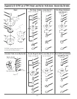
Page 34: ... before attempting any repairs 52 Important Note seal direction Apply Loctite 290 when assembling 53 54 55 53 14 6 14 1 3 1 4 First Stage Holddown Assembly 6 Discharge First Stage Holddown Assembly 6 Suction with Unloader Suction Standard Second Stage Holddown Assembly 3 1 4 Discharge Second Stage Holddown Assembly 3 1 4 Suction with Unloader Suction Standard Unloader Piston Assembly Details Figur...

Page 35: ...143 a O ring 29 3569 Valve cage 30 3689c Actuator Ref No Part No Description 31 3690c Spring 32 3689 X Unloader assembly 3 1 4 33 2438 X Suction valve assembly 3 1 4 34 1418 2b Valve gasket 35 2439 X Discharge valve assembly 3 1 4 36 3827 Valve seat 6 37 3828 Stud 38 3830d Outer valve plate 39 3831d Inner valve plate 40 3829d Spring 41 3805 X1 Valve repair kit 42 3826 Valve bumper 6 43 2446 Bolt 4...

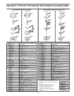
Page 36: ...20 17 21 22 23 24 25 26 27 26 22 23 24 25 21 27 Appendix E D891 and T891 Head and Valve Holddown Assembly Details Head Holddown Assembly 4 1 2 Suction with Unloader Suction Standard CAUTION Always relieve pressure in the unit before attempting any repairs Valve Assemblies 4 1 2 Suction Valve Discharge Valve Unloader Assembly Part Details Figure A Holddown Assembly 4 1 2 Discharge 36 ...

Page 37: ... 3694 X Unloader assembly 4 1 2 16 3732 X Suction valve assembly 4 1 2 17 2114b Valve gasket a _ denotes O ring code See O ring chart below for details b Included with valve assembly c Included with unloader assembly d Included with valve repair kit e Registered trademark of the DuPont company Ref No Part No Description 18 2714 1 Valve cap 19 3569 Valve cage 20 3733 X Discharge valve assembly 4 1 ...

Page 38: ...756 3 1739 3 Peek rings opt 5 1753 1757 1740 Expander ring 4 6 3604 Lock nut torque to 150 ft lbs 1 7 3730 Thrust washer 2 8 3879a 6 diameter 3884a 3 1 4 diameter 3925a 4 1 2 diameter Piston 1 9 3603 Shim washer thick As req 3603 1 Shim washer thin 10 3812 not shown Loctite tube 620 1 Model Y Bottom Min c Y Bottom Max c X Top Min b X Top Max b D791 D891 0 010 0 25 mm 0 020 0 50 mm 0 084 2 13 mm 0 ...

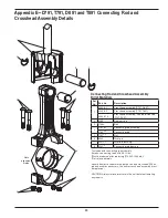
Page 39: ... assembly 3785a d Connecting rod 5 1727a b Nut 6 3540 Wrist pin 7 3541a c Wrist pin bushing 8 3542a Connecting rod bearing Connecting Rod and Crosshead Assembly Bill of Materials a Included with connecting rod assembly b Torque connecting rod nut to 40 ft lbs c Must be rebored after replacing 1 1258 1 1254 dia d Not sold separately Never attempt to separate the piston rod and crosshead When repair...

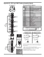
Page 40: ...nkcase 10 11 12 11 13 14 15 11 10 17 Radial Tangent Radial Tangent Radial Tangent Tangent Tangent Upper Segmented Packing Set Lower V ring Packing Set Lower V ring Packing Set 1 2 3 4 5 6 3 4 5 6 3 4 5 6 3 4 5 1 6 7 8 16 Radial Tangent Radial Tangent Radial Tangent Tangent Tangent Upper Segmented Packing Set 9 9 Appendix E D791 and D891 Packing Assembly Details Specification K Specification J 40 ...

Page 41: ...1723 Female packing ring 16 3810 X1d Segmented packing set 17 1725 2X V ring packing set Identification of Packing Specification Example Model Number D891 K M4FBA Packing Spec IMPORTANT Identify and line up the rings before installing Be sure they face the way shown here and that the pin and hole are aligned when assembled a _ denotes O ring code See O ring chart for details b Deflector ring is lo...

Page 42: ...1 14 12 15 16 20 11 17 11 12 1 2 3 8 18 9 10 13 14 19 15 13 4 5 6 5 3 4 5 6 6 7 6 3 4 11 10 10 11 Lower V ring Packing Set 19 Middle V ring Packing Set Upper Segmented Packing Set 11 11 15 12 16 14 17 11 12 1 2 3 8 18 9 10 13 14 19 15 13 4 5 6 5 3 4 5 6 6 7 6 3 4 11 10 10 11 Lower V ring Packing Set 19 Middle V ring Packing Set Radial Tangent Radial Tangent Radial Tangent Tangent Tangent 3 4 3 4 2...

Page 43: ...31 Spring 13 1724 Male packing ring 14 1725 V ring packing 15 1723 Female packing ring 16 4746 Cartridge 17 1722 X Adjusting screw 18 3810 X1d Segmented packing set 19 1725 2X V ring packing set 20 1732 Oil deflector ring Identification of Packing Specification Example Model Number T891 G L4FBDNSNC Packing Spec IMPORTANT Identify and line up the rings before installing Be sure they face the way sh...

Page 44: ...16 13 1761 Gasket crankcase 1 14 1760 Gasket inspection cover 1 15 1721 Inspection cover 1 16 7012 010NC025B Bolt 10 24 x 1 4 Phillips hd 10 17 2 231_a O ring 2 Crosshead Guide Bill of Materials Appendix E D791 Crosshead Guide Assembly Details a _ denotes O ring code See O ring chart above for details b Registered trademark of the DuPont company CAUTION Always relieve pressure in the unit before a...

Page 45: ...A Bolt 1 2 13 x 1 3 4 ferry head 16 13 1761 Gasket crankcase 1 14 1760 Gasket inspection cover 1 15 1721 Inspection cover 1 16 7012 010NC025B Screw 10 24 x 1 4 Phillips hd 10 17 2 231_a O ring 2 Crosshead Guide Bill of Materials Appendix E D891 Crosshead Guide Assembly Details a _ denotes O ring code See O ring chart above for details b Registered trademark of the DuPont company CAUTION Always rel...

Page 46: ...asket crankcase 1 15 1760 Gasket inspection cover 1 16 1721 Inspection cover 1 17 7012 010NC025B Bolt 10 24 x 1 4 Phillips hd 10 18 2 238_a O ring 2 19 1749 Cartridge holddown screw 2 20 4747 Cage 2 21 2 233_a O ring 2 22 1732 Oil deflector ring 2 Crosshead Guide Bill of Materials Appendix E T791 Crosshead Guide Assembly Details a _ denotes O ring code See O ring chart above for details b Register...

Page 47: ...sket inspection cover 1 16 1721 Inspection cover 1 17 7012 010NC025B Bolt 10 24 x 1 4 Phillips hd 10 18 2 238_a O ring 2 19 1749 Cartridge holddown screw 2 20 4747 Cage 2 21 2 233_a O ring 2 22 1732 Oil deflector ring 2 Crosshead Guide Bill of Materials Appendix E T891 Crosshead Guide Assembly Details a _ denotes O ring code See O ring chart above for details b Registered trademark of the DuPont c...

Page 48: ...4 45 46 47 48 42 51 49 56 50 36 32 59 55 33 60 62 42 28 55 61 Includes all parts shown except 52 and 53 50 58 Inside of Bearing Carrier Pump Cover Oil Filter Adapter Oil Passage Hole Important Line up hole in gasket with oil passage hole Pumpside of adapter shown for proper orientation of cover and location of pump cover pin 57 55 60 28 Appendix E Crankcase Assembly Details 48 ...

Page 49: ...93 Relief valve ball 42 4222 Xb Oil filter adapter assembly w pin 43 2 228_c O ring 44 2849 1Xb Oil pump assembly 45 2851 Spring guide 46 2852 Oil pump spring Crankcase Assembly Bill of Materials Assembly Number Assembly Name 3221 X1 Crankcase assembly M 4 8 9 without lubricator 3221 X2 Crankcase assembly M7 78 without lubricator 3221 X3 Crankcase assembly L 4 8 9 with lubricator 3221 X4 Crankcase...

Page 50: ... Number Assembly Name 3852 X Flywheel assembly flywheel hub and three bolts 3852 Flywheel 21 2 O D 5 groove H J 2 125 Hub with three bolts and lockwashers Flywheel Assembly Bill of Materials Appendix E Flywheel Assembly Details 50 ...

Page 51: ...51 ...

Page 52: ...19 CORKEN INC A Unit of IDEX Corporation 3805 NW 36th Street Oklahoma City OK 73112 Phone 405 946 5576 Fax 405 948 7343 Visit our website at www corken com or e mail us at cocsalesdept idexcorp com Solutions beyond products CorkenInc ...

Reviews: