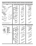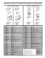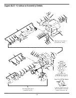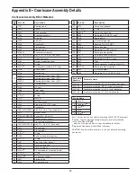
Appendix E—D891 and T891 Head and Valve Holddown Assembly Details
Compressor Head and Valve Bill of Materials
Ref
No.
Part No.
Description
1.
3923
Cylinder cap
2.
3924
Cylinder head (4-1/2")
3.
2-246
a
O-ring
4.
7001-050 NC150A
Bolt (1/2 - 13 x 1-1/2" hex head Gr 5)
(Torque to 65 ft•lbs)
5.
2598-1
c
Unloader cap
6.
2-031
a
O-ring
7.
3696
c
Unloader piston
8.
2715
Holddown screw
9.
7001-043 NC150A
Bolt (7/16 - 14 x 1-1/2" hex head)(Torque
to 37 ft•lbs)
10.
1764
Valve cover plate
11.
2-235
a
O-ring
12.
3570-1
Valve cage
13.
3694
c
Actuator
14.
3695
c
Spring
15.
3694-X
Unloader assembly (4-1/2
"
)
16.
3732-X
Suction valve assembly (4-1/2")
17.
2114
b
Valve gasket
a
_ denotes O-ring code. See O-ring chart below for details.
b
Included with valve assembly
c
Included with unloader assembly
d
Included with valve repair kit.
e
Registered trademark of the DuPont company.
Ref
No.
Part No.
Description
18.
2714-1
Valve cap
19.
3569
Valve cage
20.
3733-X
Discharge valve assembly (4-1/2")
21.
3827
Valve seat (4-1/2")
22.
3828
Stud
23.
3830
d
Valve plate (outer)
24.
3831
d
Valve plate (inner)
25.
3829
d
Spring
26.
3826
Valve bumper (4-1/2")
27.
3805-X1
Valve repair kit
28.
1910
c
Bolt
29.
2619-X
c
Unloader piston seal assembly
30.
2857
c
Unloader piston cap
31.
2858
c
Gasket
O-ring Code
A
Buna-N
B
Neoprene
®e
D
Viton
®e
E
PTFE
K
Kalrez
®e
37

