2C9
1-6-26
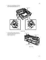
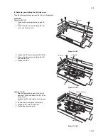
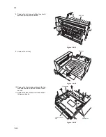
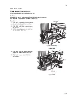
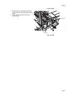
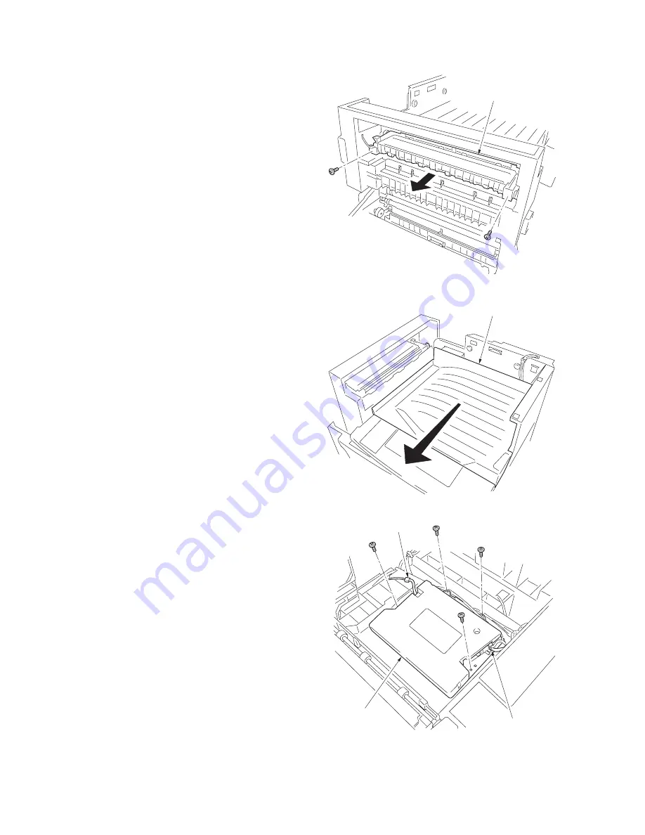
8. Remove the two screws holding the exit unit
and then pull out the unit a little.
Figure 1-6-51
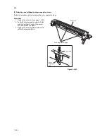
9. Remove the exit tray.
Figure 1-6-52
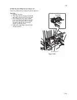
10. Remove the four screws and detach the two
connector and then remove the laser scan-
ner unit.
11. Replace the laser scanner unit and refit all
the removed parts.
Figure 1-6-53
Exit unit
Exit tray
Laser scanner
unit
Connector
Connector
Summary of Contents for CS-1620
Page 1: ...SERVICE MANUAL Published in June 05 2C970946 Revision 6 CS 1620 2020...
Page 4: ...This page is intentionally left blank...
Page 10: ...This page is intentionally left blank...
Page 48: ...2C9 4 1 4 7 This page is intentionally left blank...
Page 61: ...2C9 4 1 4 18 This page is intentionally left blank...
Page 73: ...2C9 4 1 4 28 This page is intentionally left blank...
Page 84: ...2C9 4 1 4 37 This page is intentionally left blank...
Page 94: ...2C9 4 1 4 45 This page is intentionally left blank...
Page 147: ...2C9 4 1 6 16 This page is intentionally left blank...
Page 173: ...2C9 6 0 1 6 40 This page is intentionally left blank...
Page 235: ......

