Cooper Crouse-Hinds GmbH
11
11
11
11
11
2
Safety instructions
The safety switches are not
suitable for Zone 0 and Zone 20
hazardous areas.
The temperature class and explosion
group marked on the apparatus shall be
observed.
To ensure adherence to the temperature
class stated on the type label of the
apparatus, the permissible ambient
temperature, the rated terminal cross
section and the self-heating of the
apparatus, that is mainly due to the power
dissipation, shall be taken into account
(test criterion for the self-heating is an
overload of 10%).
Modifications or changes to the safety
switches are not permitted.
They shall be used for their intended
purpose and in a perfect and clean state.
The apparatus shall not be used in dust
layers > 50mm acc. to EN 50 281-1-2.
Only original CCH / CEAG parts may be
used as replacements and for repairs.
Explosion-protected safety switches for variable
frequency drives, 20A - 180A
Repairs that affect the explosion
protection may only be carried out by
CCH / CEAG or by a qualified electrician in
compliance with the respective national
regulations.
Prior to being put into operation, the
control units shall be checked in acc. with
the instructions as per section 6.
Before initial operation, any foreign matter
shall be removed from the apparatus.
Warning:
The covers of the safety switches can only
be removed when the switch is in the “ON”
position.
The safety switches can be switched off
only after having „unlocked“ the
interlocking switch.
Attention!
When opening the interlocking switch, the
drive is switched off.
The national safety rules and regulations
for the prevention of accidents, as well as
the safety instructions included in these
operating instructions, that, like this text,
are set in italics, shall be observed!
3
Conformity with standards
The safety switches meet the requirements of
EN 50 014, EN 50 018, EN 50 019, EN 50 020
and EN 50 281-1-1 (comparable international
standards IEC 60079-0, IEC 60079-1,
IEC 60079-7, IEC 60079-11, IEC 60079-14).
94/9 EC: Equipment and protective systems
intended for use in potentially explosive
atmospheres.
The safety switches fulfil further requirements,
such as those of the EC directive on
electromagnetic compatibility (89/336/EEC).
They have been designed, manufactured and
tested according to the state of the art and to
DIN EN ISO 9001.
4
Field of application
The safety switches are intended for use in
potentially explosive atmospheres in Zones 1
and 2 as well as in Zones 21 and 22 in
accordance with IEC 60079-10.
The enclosure materials used, including any
external metal parts, are high quality materials
that ensure a corrosion resistance and
resistance to chemical substances according
to the requirements for use in a “normal
industrial atmosphere”:
- glass-fibre reinforced polyester
- impact resistant polyamide
- special steel AISI 316 L.
When used in extremely aggressive
atmospheres, the additional data relating to
the chemical resistance of the plastics being
used shall be taken from the data sheet
GHG 902 4001 P0001.
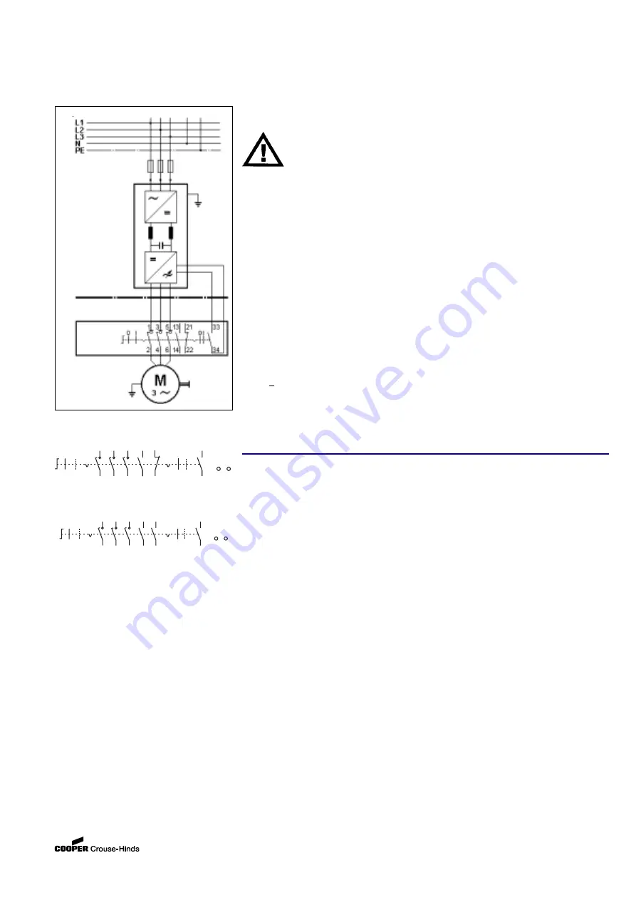
Fig. 5
Ex
Area
Non - Ex
Area
Safety switch
Wiring diagrams
3-pole + 1NO + 1NC
3-pole + 2 NO
5
Application / Properties
The safety switches for variable speed drives
are used for the safe, all-pole isolation of
electrical power when maintenance, cleaning
and repair work is carried out on systems,
machinery and drives operating on frequency-
controlled converter drives in hazardous areas.
See technical data for the temperature class,
explosion group and permissible ambient
temperature.
With frequencies up to f 40 Hz and from
about 60 to max. 200 Hz, the main switch must
be switched without load to avoid damages.
Any damage to the switch within the lower
frequency range (zero point erasing) as well as
within the upper frequency range (restriking) is
thus prevented.
The time delay required for switching off the
converter (approx. 1 second) is achieved by
means of a compulsory mechanical
interlocking auxiliary switch. See also
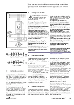
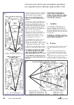
functional diagram, Fig. 1 and Fig. 2, page 9.
Due to the compulsory mechanical
interlocking, a maloperation of the switch is
not possible without destroying it.
In addition to this, the safety switches are
fitted with auxiliary contacts (1 N/O and 1 N/C),
that, in relation to the main contacts, are
lagging / leading during making and leading /
lagging during breaking.
0 I
30° 90°
1
2
5
3
13
4
6
14
N PE
22
21
0 I
33
34
0 I
30° 90°
1
2
5
3
13
4
6
14
N PE
0 I
33
34
23
24


