background image

62

www.cooperbussmann.com/wirelessresources

Cooper Bussmann 915U-2 Wireless Mesh I/O and Gateway User Manual

Rev Version 1.2.2

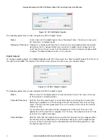
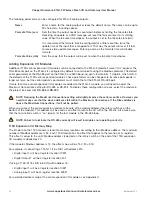
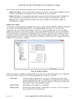
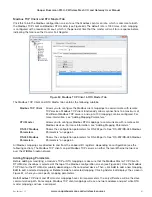
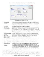
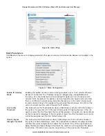
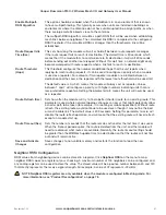
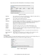
Figure 61  Modbus TCP Client Mapping

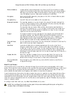
Local Register 
(Master)

When the Function Code Modbus command is “Read” the Local Register field will 
be the destination register  (output location) on the local device. When the Function 
Code command is  “Write” the Local Register field will be the originating register 
(input location) on the local device.

I/O Count

The number of consecutive I/O values in the mapping.

Function Code 
(Command Type)

The Function Code Modbus command determines if the command will be “Read” or 
“Write” and what type of register will be used. When entering a mapping, you need 
to select “Read” or “Write” from the drop-down list in the Command Type field, and 
then select one of the four radio buttons representing the register types. Selecting the 
register type will change the Destination (slave) register address range to a suitable 
range.

Destination Register 
(Slave)

The register location on the TCP server/RTU slave device. The register selection 
offered will be appropriate for the Modbus command selected in the Command field.

Device ID

The unit address (device ID) of the Modbus TCP server or Modbus RTU slave.

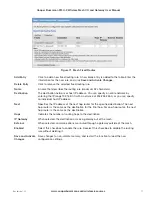
Server IP Address  
Network Address

(TCP client only.) The IP address of the Modbus TCP server.

Server Port (TCP 
Client only)

The server port of the slave device, Modbus TCP will usually be the standard port 
address of 502. 

Serial Port (Modbus 
RTU only)

This is the serial port used to connect to the device. Select the port from the 
drop-down list. 

Response Time

The amount of time the TCP client or Modbus master waits for a response from a 
TCP server or an RTU slave device before registering a Communications Fail. 

Fail Reg

The Comms Fail indication register can be a physical output, such as DIO #1–8 (Reg 
1-8), which will turn on a digital output when in fail. It can also be configured as an 
internal holding register (Reg 30501), which will show the fail indication as well as 
any Modbus error codes. This is useful for diagnosing communication problems. For 
Modbus error code descriptions, see Appendix D.

Modbus TCP Mapping Examples

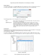
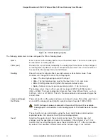
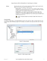
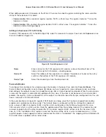
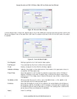
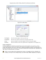
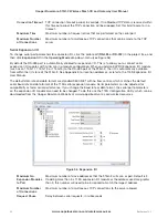
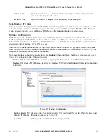
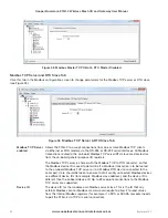
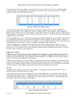
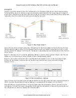
In the example in Figure 62, the first mapping (#1) shows the Modbus client (master) is configured to read analog 
values from a device connected on the LAN. The mappings function code is “Read” and is reading a count of four 
values (analogs) from the Ethernet address 192,168.0.17, device ID #10, starting at address 30001, and then writing 

Summary of Contents for 915U-2

Page 1: ...Read and Retain for Future Reference Cooper Bussmann 915U 2 Wireless Mesh I O and Gateway User Manual Version 1 2 2 ...

Page 2: ...lt of its actions in Docket 93 62 and OET Bulletin 65 Edition 97 01 GNU Free Documentation License Copyright C 2009 Cooper Bussmann Cooper Bussmann is using a part of Free Software code under the GNU General Public License in operating the 915U 2 product This General Public License applies to most of the Free Software Foundation s code and to any other program whose authors commit by using it The ...

Page 3: ...o operate the device This device must be installed by professional installers in compliance with 47 CFR Part 15 Subpart C Section 15 203 and 15 205 who will be responsible for maintaining EIRP no greater than 36 dBm in accordance with 47 CFR Part 15 Subpart C Section 15 247 b 2 4 In accordance with 47 CFR Part 15 Subpart C Section 15 203 only the following antenna coax cable kits combinations can ...

Page 4: ...isuse age or malfunction We recommend that users and designers design systems using design techniques intended to prevent personal injury or damage during product operation and provide failure tolerant systems to prevent personal injury or damage in the event of product failure Designers must warn users of the equipment or systems if adequate protection against failure has not been included in the...

Page 5: ...rsion 1 2 2 which applies to version 1 2 2 firmware Follow Instructions Read this entire manual and all other publications pertaining to the work to be performed before installing operating or servicing this equipment Practice all plant and safety instructions and precautions Failure to follow the instructions can cause personal injury and or property damage Proper Use Any unauthorized modificatio...

Page 6: ...D Indicators 28 3 3 System Design 29 Radio Channel Capacity 29 Dual Band Operation 29 Radio Path Reliability 29 Design for Failures 30 Indicating a Communications Problem 30 WIBNet Communication Registers 31 Testing and Commissioning 31 3 4 WIBMesh 31 Chapter 4 CONFIGURATION 32 4 1 Connecting to the Module 32 4 2 MConfig Utility 34 Downloading and Installing MConfig 34 Starting MConfig 35 Project ...

Page 7: ...g 85 Trace Route 85 5 6 Mesh Network Statistics 86 5 7 Monitor Communications 88 Monitor WIBMesh Radio Communications 88 Monitor WIBMesh IP Comms 89 Monitor WIBNet Radio Comms 90 5 8 Statistics for WIBMesh and WIBNet 91 Chapter 6 SPECIFICATIONS 92 Appendix A DBM TO MW CONVERSION 94 Appendix B I O STORE REGISTERS 95 Output Coils 95 Input Bits 95 Input Registers 95 Holding Registers 96 Appendix C EX...

Page 8: ...urable value referred to as sensitivity The default sensitivity is 1000 counts 3 but this value can be changed using the Sensitivity Block configuration page in the MConfig Utility as described in Sensitivity Blocks on page 55 In addition to COS messages update messages are automatically transmitted on a configurable time basis These updates ensure system integrity Pulse inputs counts are accumula...

Page 9: ...ovides services for other processes within the module The I O store is split into eight different blocks types Two blocks made available for bit data discrete Two blocks made available for word data analog Two blocks made available for 32 bit words data 32 bit analogs Two blocks made available for floating point data floats Each of these block types in turn support input and output locations that ...

Page 10: ...ge of the connected expansion modules displayed as an analog value RSSI The radio signal level for the selectable address reported as a dB level Comms Fail A selectable register can indicate a Communications Fail error for a particular message transmission The expansion port allows 115S expansion I O modules to be added to the module Expansion I O is dynamically added to the internal I O of the 91...

Page 11: ... to the SUP and SUP terminals 12 15 Vdc power source rated at 24W connected to the BAT and GND terminals A primary power supply connected to the SUP and SUP terminals automatically charges a 13 8V sealed lead acid battery if connected to the BAT and GND terminals at up to 1A at ambient room temperature 25 C Battery charge current is reduced to 0 5A at 60 C If using a battery it is recommended that...

Page 12: ...575 mA Battery charging N A 575 mA The following table shows typical 24V supply current limits with different module options enabled Transmit current is not added because it is not a constant Expansion I O No Expansion I O No battery fitted no charging 1270 mA 695 mA Battery fitted 1555 mA 980 mA The following table shows typical 13 8V supply current limits with different module options enabled Tr...

Page 13: ...ls The values can also be mapped to a register or an analog output on another module within the radio network Register Description 30005 Local supply voltage 0 40V scaling 30006 Local 24V loop voltage 0 40V scaling Internally generated 24V supply used for analog loop supply Maximum current limit is 100 mA 30007 Local battery voltage 0 40V scaling 30008 115S supply voltage 0 40V scaling 38005 38008...

Page 14: ... displays the frequency bands available for the model and country For details see Radio Settings on page 69 The receiver is continually scanning all channels within the hopset and when a valid data packet is received it locks on to the channel and receives the data A spread spectrum transmission offers the following advantages over a fixed frequency transmission Spread spectrum signals are more re...

Page 15: ...line of sight path Because of the curvature of the earth the antennas need to be elevated at least 15 feet 5m above ground for paths greater than 3 miles 5 km The modules will operate reliably with some obstruction of the radio path although the reliable distance is reduced Obstructions that are close to either antenna have a greater blocking effect than obstructions in the middle of the radio pat...

Page 16: ...e is a common cause for problems with radio systems because it greatly increases radio losses We recommend that the connection be taped first with a layer of PVC tape next with a vulcanizing tape such as 3M 23 tape and finally with another layer of PVC UV stabilized insulating tape The first layer of tape allows the joint to be easily inspected when troubleshooting because the vulcanizing seal can...

Page 17: ...rovides a double improvement Yagi antennas are directional That is they have positive gain to the front of the antenna but negative gain in other directions Therefore Yagi antennas should be installed with the central beam horizontal and must be pointed precisely in the direction of transmission to benefit from the gain of the antenna The Yagi antennas may be installed with the elements in a verti...

Page 18: ...ole should be located on the bottom of the installed antenna 2 5 Connections Bottom Panel Connections Figure 9 Bottom Panel Connections Ethernet Port The 915U 2 modules provides a standard RJ 45 Ethernet port compliant to IEEE 802 3 10 100BaseT This port provides full access to the module including configuration diagnostics log file download and firmware upload of both the local and remote units A...

Page 19: ...o 915U 2 7 CTS Clear to Send 8 RTS Request to Send RS 485 port with Modbus Support The 915U 2 module provides an RS 485 serial port that supports operations at data rates up to 230 400 baud The default baud rate is 9600 baud no parity 8 data bits and 1 stop bit which matches the 115S serial expansion module defaults This port supports the Modbus protocol The RS 485 port terminal is hosted on the f...

Page 20: ... USB storage devices for upgrading the module firmware For details see System Tools on page 74 DIP Switches The DIP switches are used to select a number of functions within the module as shown in the following table DIP switches 1 to 2 Used for measuring current or voltage on analog input 3 Set DIP switches to on to measure current 0 20 mA and off for voltage 0 5 Vdc DIP switches 3 to 4 Used for m...

Page 21: ...Panel Connections Digital or Pulsed Inputs Each digital I O channel on the 915U 2 module can act as either an input or an output The input output direction is automatically determined by the connections and configuration of the I O If you have an I O channel wired as an input but operate the channel as an output no electrical damage will occur but the I O system will not operate correctly For exam...

Page 22: ...sistor 1KΩ to V Pulsed inputs are converted to two different values internally The first value is the pulse count which is an indication of how many times the input has changed state over a configured time period The second value is a pulse rate which is an analog input derived from the pulse frequency For example 0 Hz 4 mA and 1 kHz 20 mA All pulsed input counts are stored in non volatile RAM so ...

Page 23: ...e is the time the output counts down before activating a fail safe state Normally this would be configured for a little more than twice the update time of the mapping that is sending data to it This is because the fail safe timer is restarted whenever it receives an update If you send two successive updates and fail to receive both of these messages the timer counts down to zero and activates the ...

Page 24: ... Utility For more information see Analog Inputs on page 23 The LEDs next to AI1 AI2 flash according to the current on these inputs The LEDs next to AI1 and AI2 flash according to the voltage on the analog inputs Differential Current Inputs Only analog input 1 and 2 can be wired as differential Inputs Differential mode current inputs should be used when measuring a current loop which cannot be conn...

Page 25: ... to the 915U 2 module Devices can be powered from the 24V analog loop supply ALS generated internally from the module The DIP switches located in the side access panel are used to determine if the inputs will be current or voltage DIP switches 1 and 2 are used for analog 3 and DIP switches 3 and 4 are used for analog 4 For current set both DIP switches to the on position For voltage set both to of...

Page 26: ... 4 gives 0 5V for 4 20 mA output For voltage input on analog 3 and 4 set both DIP switches to the off position Figure 20 Voltage Inputs Analog Outputs The 915U 2 module provides two 0 24 mA DC analog outputs for connecting to analog inputs on equipment such as PLCs DCS and loggers or connecting to instrument indicators for displaying remote analog measurements The 915U 2 analog outputs are a sourc...

Page 27: ...t PWR Fast Flash System boot stage 1 PWR Slow Flash System boot stage 2 RF Orange Transmitting radio data RF Red Receiving radio data 232 Green Transmitting RS 232 data 232 Red Receiving RS 232 data 232 Orange Transmitting and receiving RS 232 data 485 Green Transmitting RS 485 data 485 Red Receiving RS 485 data The RF LED does not directly represent the actual radio transmission status It only in...

Page 28: ...tal Output Configuration page in MConfig Utility is off See Fail safe Blocks on page 53 for details Analog Inputs There are two LEDs for each differential analog input The first LED is used to indicate that the analog input is reading a current mA The second LED indicates that the input is reading voltage Each of the analog input LEDs flash with increasing speed and intensity depending on the leve...

Page 29: ... utilize the full 902 928 MHz bandwidth such as the United States and Canada the 915U 2 uses both sub bands which makes it possible to force the frequency hopping to the other band high or low to avoid radio interference and to separate systems In other countries such as Australia and New Zealand this option is unavailable because of the single band Radio Path Reliability Radio paths over short di...

Page 30: ...Mappings on page 42 Fail to transmit Alarm The first method is to setup a communications indication on a register of your choice when configuring a mapping This can be done using an existing mapping no need to setup a special communications mapping When entering a block write or gather scatter mapping enter a register location for a communications failure in the Fail Register field This register c...

Page 31: ...Mesh protocol is based on the Ad hoc On demand Distance Vector AODV routing algorithm a routing protocol designed for ad hoc networks AODV is capable of unicast single addressed message routing and is an on demand protocol meaning that it builds and maintains these routes only as long as they are needed by the source devices In other words the network is silent until a connection is needed The pro...

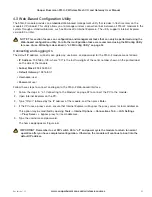
Page 32: ...o IP address are as follows IP Address 192 168 0 1XX where XX is the last two digits of the serial number shown on the printed label on the side of the module Subnet Mask 255 255 255 0 Default Gateway 192 168 0 1 Radio IP Address 192 168 2 1 1 Connect a straight through Ethernet cable between the module s Ethernet port and the PC 2 Restore the module s default settings if they are not the current ...

Page 33: ...subnet mask 255 255 255 0 and then click OK Figure 26 TCP IP Properties 7 Verify the Ethernet connection to the module by using the ping command c From the Windows Start menu choose Run and then type command A command prompt DOS window appears d Type ping 192 168 0 1XX where XX is the last two digits of the serial number shown on the printed label on the side of the module The ping response should...

Page 34: ...nt You can also configure advanced settings including Over the radio link configuration and diagnostics Gateway functionality for Modbus TCP and RTU protocols Radio communications monitoring I O point naming Downloading and Installing MConfig The MConfig Utility is provided as a zip file from the download section of the Cooper Bussmann website Configuration of the 915U 2 module can be performed vi...

Page 35: ...on project that was used on the PC All configuration project files are typically stored locally on the PC or on a network drive The path to the last project used appears below this button Open Existing Project Opens any previously saved project This can be a project that was created on the current computer or a configuration that was created elsewhere and sent to you A dialog box will allow you to...

Page 36: ...word Protection Allows you to enable or disable the security option When enabled a password is required to access to the configuration file The password must be a minimum of six characters Password protection does not provide security for the radio link This is handled through radio communication security which is configurable via the Web based configuration utility For more information see Radio ...

Page 37: ...n This field allows you to change the default radio IP address and network mask The WIBMesh protocol is an IP based protocol which means that the radio network will have an IP address range assigned to it The default network base address is 192 168 100 0 Each radio will have a radio IP address assigned to it starting at 192 168 100 1 and incrementing as each radio is added to the configuration Thi...

Page 38: ...scription and Location Details that you can add to provide information about the module Configuration Version Displays the time and date when the current firmware was last updated This information is not editable and is only updated when the module is programmed or read Radio Network Configuration Radio IP address of module as described in Adding Units to a Project IP Gateway Mode Select this opti...

Page 39: ...nto MConfig replacing the configuration currently in MConfig for this module see Figure 34 Select the method that will be used to read the configuration data from the module Ethernet Local Load the configuration from the module using the local Ethernet interface displayed in the list Select IP Address or enter a new address USB Externally Powered Load the configuration from the module using the lo...

Page 40: ...igure 35 IO Diagnostics Displaying the IP Address List Click IP Address List in the project tree to display the module name and corresponding radio and Ethernet IP address subnet mask and network address for each module in the project The IP address list is a read only screen To change a module IP address see Editing Module IP Addresses on page 41 ...

Page 41: ...ed from this default The radio IP address can also be manually edited by clicking the 915U 2 module in the project tree and then clicking Edit see Figure 32 The Ethernet IP address can be edited by clicking Ethernet in the project tree and then entering in an appropriate address and network mask This page also allows the Ethernet interface to be disabled by deselecting the Enabled checkbox In addi...

Page 42: ...ng Parameters on page 43 There are three types of mappings write gather scatter and read Each type has advantages and disadvantages The appropriate mapping to use will depend on the data and requirements of the system Write mapping A multi I O mapping allows multiple sequential values to be sent in one message If you are mapping analog values the maximum I O count is 64 However if you are mapping ...

Page 43: ...ocalhost loopback address of 127 0 0 1 IP Address This option allows any IP address to be entered in the configuration It is for advanced users only because the remote name and address location will not show up in the I O list Knowledge of the remote module s I O location and address is required for it to function correctly Generally this option is only used when a module that is not in the projec...

Page 44: ...x allows the mapping to be acknowledged when the end device receives the message This is an end to end acknowledgment and is in addition to the normal hop by hop frame acknowledgment between links NOTE Enabling this option will increase the amount of radio communications and care should be taken in larger systems Update Time Configures how often the mapping update messages check signals are sent T...

Page 45: ...nned by the internal processor and each time a scan occurs it would force the mapping to be sent If a digital input is required to be used as the trigger map the digital input to a general purpose bit storage register 501 10501 and so on and then use this general purpose register to trigger the force mapping Enable Mapping Select the checkbox to enable this mapping Apply Saves the current settings...

Page 46: ...ion Address Map The I O data store provides storage for all I O data both local data and data received from the system The I O store provides four register types two bit registers two word registers two long word registers and two floating point registers In addition each register type supports both inputs and outputs making a total of eight register addresses that are used for physical I O and ga...

Page 47: ...tery voltage 0 40V default scaling 30008 115S expansion I O supply voltage 0 40V default scaling 30009 30012 Local AI1 AI4 voltage mode AI1and AI2 0 20V AI3 and AI4 0 5V 30013 30016 Local pulse input rates PI1 PI4 36001 36008 Local pulsed input counts PI1 most significant word is 36001 and least significant word is 36002 38001 38032 Local analog inputs as floating point values mA volts or Hz 40001...

Page 48: ...creen Figure 43 where you can change settings Figure 43 IO Edit Digital Output The following parameters can be configured for 915U 2 digital outputs Name Enter a name for the digital output or leave the default name The name can be up to 30 characters including spaces Fail safe Time sec Sets the time the output needs to count down before activating the fail safe state Receiving an update or a COS ...

Page 49: ...st received value The time is related to the update time of the pulsed input that is mapped to it For example if the pulsed input update time is configured for 10 seconds the number of pulses will be counted and sent to the receiving module every 10 seconds The receiving module will then output the pulse count over the configured update time 10 seconds Analog Inputs Analog inputs have more configu...

Page 50: ...er measured value mA V Hz and so on The analog scale is linear with an overall raw range of 8192 to 49152 decimal total 40960 The input engineering range can have many different forms such as 0 20 mA 0 5V or 0 1000 Hz This why the zero and span can be scaled to give the correct value Lower and Upper Set Points These set points are the upper and lower control point values that will be used to turn ...

Page 51: ...oint will be reset off 0 Default Mode In this mode the set point operates in default mode If the analog input is greater than the Upper Set point the set point status will be active on or 1 When the analog input is less than the Lower Set point the set point will reset off or 0 NOTE The upper set point must always be higher than the lower set point Analog Outputs To configure analog outputs click ...

Page 52: ...al expansion I O modules are added to the 915U 2 module you will need to adjust the Maximum Connections setting for RS 485 or RS 232 To display these configuration screens select the module in the project tree and click RS 485 or RS 232 NOTE Reducing the Maximum Connections setting will slightly improve the serial scan time However you need to make sure that the slave addresses fall within the Max...

Page 53: ...roject tree and click Fail safe Blocks The Fail safe Block configuration screen Figure 50 allows you to set registers to a pre configured value on startup and configure the outputs to reset to a predefined value after a timeout period has elapsed When the actual value is received the register is automatically updated with this value If the value is lost because of a communication problem the regis...

Page 54: ...uts will be initialized when the module is first powered on Used in conjunction with the preset value Preset Value Value the registers are set to when the module is powered on and the Initialize at Startup checkbox is selected If a digital value is selected the preset value will be either on or off If an analog value is selected the preset value will be a value between 0 and 65535 Invalidate on Fa...

Page 55: ...fault sensitivity value of 1 The 12 analog inputs have a sensitivity of 1000 bits or approximately 3 1000 bits from a total range of 32768 3 05 The 24 floating point values have a default sensitivity of 0 5 units Inputs 38001 38004 will be 0 5 mA inputs 38005 38012 will be in volts and inputs 38013 38016 will be in hertz A sensitivity value is needed for analog inputs in order to prevent the modul...

Page 56: ... trigger occurs Serial Configuration The 915U 2 module has an RS 232 and an RS 485 port for serial communications These ports are used to connect ELPRO 115S 11 115S 12 and 115S 13 serial expansion I O modules The ports can also be used to connect external Modbus RTU master or slave devices The port operating mode and the normal serial parameters baud rate data format flow control and so on all nee...

Page 57: ...U master and polling Modbus slave devices via the selected serial port It also allows Ethernet Modbus TCP clients connected to the 915U 2 Ethernet port to communicate with Modbus RTU slave devices connected to the configured serial port The 915U 2 makes this possible by internally performing the necessary protocol conversion The conversion is performed by the 915U 2 that is directly connected to t...

Page 58: ... 13 to the RS 485 port of the 915U 2 the I O is automatically available from within the I O store of the 915U 2 See Appendix E for location addresses or refer to the 115S Expansion I O User Manual The default data rate and data format are standard 9600 N81 with no flow control which matches the default serial baud rate and data format of the 115S serial expansion module Serial parameters can be ad...

Page 59: ...ve can all be supported simultaneously When combined with the built in Modbus TCP to RTU converter the 915U 2 can transfer I O to and from almost any combination of Modbus TCP or RTU devices The 915U 2 has predefined data areas for inputs and outputs and the different I O types bits words long floats and so on which include the onboard input outputs and are shared for both client and server For a ...

Page 60: ...rom the on board general purpose I O registers The Modbus TCP server is shared with the Modbus TCP to RTU converter so that the Modbus device ID is used to determine if a Modbus transaction is to be routed to the on board Modbus TCP server or to a Modbus RTU device connected to the serial port Care should be taken to ensure that all serially connected Modbus devices use different device IDs for ex...

Page 61: ...e Adding Mapping Parameters RS 232 Modbus Parameters Shows the configuration parameters for RS 232 ports See RS 232 RS 485 Modbus Parameters on page 64 RS 485 Modbus Parameters Shows the configuration parameters for RS 485 ports See RS 232 RS 485 Modbus Parameters on page 64 All Modbus mappings are directed to and from the onboard I O registers depending on configuration see the following section ...

Page 62: ...mmand field Device ID The unit address device ID of the Modbus TCP server or Modbus RTU slave Server IP Address Network Address TCP client only The IP address of the Modbus TCP server Server Port TCP Client only The server port of the slave device Modbus TCP will usually be the standard port address of 502 Serial Port Modbus RTU only This is the serial port used to connect to the device Select the...

Page 63: ...ddress 192 168 0 17 It will write the values into the destination address 40001 and 40002 at device ID of 10 It is using the TCP server port 502 and is configured with a response time of 1000 msec If it fails to communicate it will turn on local register 505 Modbus RTU Master Modbus RTU functionality allows connections to Modbus RTU slave devices via the RS 232 or RS 485 ports The maximum number o...

Page 64: ...al battery voltage Reg 30007 to register 40001 on a serial device connected on the RS 232 with a device ID of 6 Again the response timeout is 1000 msec and it has a communications fail register of 506 Figure 64 Operating Mode Error NOTE MConfig will indicate whether the serial port Operating Mode is not set or set to the wrong mode To change the mode click the RS 232 or RS 485 Modbus Parameter tab...

Page 65: ...and password for the 915U 2 module are as follows IP Address 192 168 0 1XX where XX is the last two digits of the serial number shown on the printed label on the side of the module Subnet Mask 255 255 255 0 Default Gateway 192 168 0 1 Username user Password user Follow these steps to connect and log on to the 915U 2 Web based interface 1 Follow the steps in 4 1 Connecting to the Module on page 32 ...

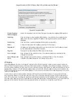
Page 66: ...ternal Ethernet network All traffic for the external network must be routed through this IP address Link Quality Threshold The radio will use this threshold level when establishing a mesh link with other radios in the system It represents a 0 100 level of link quality 100 being the best If the link quality is lower than the threshold the link will be ignored Link quality can be monitored on the Co...

Page 67: ...gure a priority with higher numbers indicating units that are less preferred as repeaters Setting the parameter to 8 means the unit will never be used as a repeater Route Refresh Sec Sets how often the module will try to find a better shorter route for an existing route This parameter is used where network topology changes can occur that might potentially allow a shorter path to be taken for examp...

Page 68: ... the reboot sequence all changes are in effect IP Routing Click IP Routing on the menu to change IP routing to other 915U 2 modules in other wired or wireless networks When a 915U 2 module receives an IP frame that is destined for an IP address on a different network it checks to see if the network address matches one of its own interfaces hard wired Ethernet or radio and forwards the frame approp...

Page 69: ...5 Netmask Subnet mask for the destination network Interface The interface to use for the route You can choose Radio Ethernet or Any Gateway Specifies the IP address of the next hop router for the specified destination Enabled Select this checkbox to enable the routing rule Deselect this checkbox to disable the routing rule without deleting it Save Changes Save changes to non volatile memory The mo...

Page 70: ... is available depending on the country code Fixed frequency models EU can use 14 38 56 and 76 kbps The FHSS US AU NZ and IN use 19 56 76 and 115 kbps The communicating radio can be configured with a different data rate and will communicate at whatever rate is configured The advantage of using the higher date rate is an increase in speed but this is offset by a decrease in range Disable Rx LNA Sele...

Page 71: ... with a netmask of 255 255 255 0 or you can specify an individual host IP address Next Specifies the IP address of the next hop router for the specified destination The next hop router is the same as the destination for the final hop For one hop routes the next hop router is the same as the destination Hops Indicates the number of routing hops to the destination IP Gateway When selected the destin...

Page 72: ...heckboxes are deselected because the destination will be the local I O on 10 0 0 2 Entry 2 is similar to entry 1 except the destination address is 10 0 0 3 and the number of hops is two The next address is 10 0 0 2 because all communications will pass through Repeater Site 2 Entry 3 is also similar to entries 1 and 2 except the destination address is 10 0 0 4 and the number of hops is three The ne...

Page 73: ...communicating via 10 0 0 2 Site 2 and 10 0 0 3 Site 3 Figure 75 Trace Route Example 2 Figure 77 shows the routing rules for the example in Figure 76 The first route indicates that the destination and next addresses are both 10 0 0 1 because it is a single hop The destination is a gateway on an external network therefore the IP Gateway checkbox must be selected The second routing rules shows the de...

Page 74: ...me given to the module if it is used with a DHCP client Owner Module owner name Contact Contact details can include a phone number email address and so on Description Description of the module Location Physical location of the module Configuration Version Configuration version description System Tools Click System Tools on the menu to perform administrative tasks such as clearing the system log re...

Page 75: ...t was not successful repeat the process The module will verify that the file is valid before a reset can be initiated NOTE All existing configuration parameters will be saved However if any new parameters are added to the firmware the default values will be used Figure 79 Firmware Upgrade Full Firmware Upgrade Firmware can also be upgraded using a USB flash drive containing the firmware files A fu...

Page 76: ...e PC Right click the drive and select Format from the menu Figure 80 Formating USB Flash Drive 2 Make sure that Quick Format is not selected and then click Start Figure 81 Quick Format 3 When formatting is complete copy the supplied firmware files to the USB flash drive root directory The files should look similar to Figure 82 Figure 82 Firmware Files 4 Remove the USB flash drive from the PC ...

Page 77: ...he 915U 2 if it is currently powered on 3 Remove the cover from the small access panel on side of module to reveal a USB port and switches Figure 84 Module USB Port and Switches 4 Plug USB stick into USB port and power on the 915U 2 module 5 The PWR LED will flash as indicated in Figure 85 NOTE Do not remove the flash drive or interrupt power to the module while the upgrade is in progress If the u...

Page 78: ...compatibility mode will allow communications with ELPRO E Series wireless I O modules 3 When prompted click Reset Unit When the reset is complete the module will be in the selected mode Figure 86 Product Reconfiguration Feature License Keys Feature license keys allow you to upgrade the 915U 2 module with enhanced features or to a more advanced model for example by enabling the Modbus option The fe...

Page 79: ...et again After the module resets the message Active appears indicating that the demonstration mode is activated Feature License Keys Upgrades or advanced features are made available by entering the purchased feature license key into the appropriate box next to the feature or enhancement After entering the code click Save Changes and Reset If the code is valid a green checkmark appears If the code ...

Page 80: ...og outputs to 20 mA NOTE If the value appears at the bottom of the page when reading a register it indicates that the register has not been written to and therefore has no value not even zero A mapping will only be sent when all registers have a value To set an initial value for registers upon startup use the Fail safe Block Configuration menu in the Web based configuration utility or use the MCon...

Page 81: ...g processes Watchdog Processes A00 Internal process monitor A01 I O processing application A02 Fail safe manager application A03 Modbus application A04 I O mapping application A06 AODV meshing protocol application A07 Data logging application A15 Warm restart backup Module Information Registers Certain registers in the module show modules characteristics such as the serial number firmware version ...

Page 82: ...Codes As per Appendix D 30019 Offset Modbus Lost Link Counter number of Communication Errors 30020 Offset Modbus Module Type dec 257 101hex indicates a 115S 11 dec 513 201hex indicates a 115S 12 dec 769 301hex indicates a 115S 13 5 2 Mesh Connectivity Click the Connectivity link from the home page of the Web based configuration utility to display connections and available networks The Connected De...

Page 83: ...outside the local network Iface The connection interface er0 Ethernet radio eth0 Ethernet LAN Age H M S This is the timeout of the message in hours minutes and seconds Link Quality Indicator Because a typical frame is around 80 bytes 4480 bits you should not typically see link quality indicator LQI readings between 75 and 99 Communication becomes unreliable when the LQI drops to 30 As the LQI drop...

Page 84: ...e units see Figure 91 However if the graph shows large dips typically one or two across several channels there is multipath fading see Figure 92 Figure 91 Neighbor RSSI No Multipath Fading Figure 92 Neighbor RSSI Multipath Fading RSSI is gathered from the normal radio communications at the site If communications is sparse the graph may take time to fill all channels If the graph is not filling aft...

Page 85: ...aximum ping times in milliseconds A ping can be performed on either the radio network or the Ethernet network The ping command will automatically select the correct network interface according to the address selected When pinging on the radio network the response time for the first ping will be longer if the device needs to establish a network route to the destination The information for the first...

Page 86: ...e 874 ms A roundtrip response time ping in milliseconds from the Host IP to each hop point 5 6 Mesh Network Statistics If you select the Statistics Gathering option on the Network configuration page see Figure 95 you can then use the Network Statistics page to display the average receive and transmit throughput levels over a configured time period On the Network Statistics page select the sample p...

Page 87: ...eive r data on an hourly scale in accordance with the module Date and time stamp The letters rt indicate both transmit and receive The table below the graph shows the average data throughput in packets for transmit and receive for each hour See Figure 98 Daily or Weekly These options show the average throughput over the daily or weekly time period They also show the average number of packet receiv...

Page 88: ...Weekly Statistics 5 7 Monitor Communications Monitor WIBMesh Radio Communications Click Monitor Radio Comms on the home page of the Web based configuration utility to view communication frames that are received or transmitted by the radio Figure 100 NOTE Corrupted data frames are shown with an ERROR in the frame Figure 100 Monitor Radio Comms ...

Page 89: ...ed message or internal sequence number for the transmitted message Data Length Total length of the transmitted or received message Data The TX data frame in the example contains the following First two bytes 80 B1 Frame flags Second two bytes 34 86 Network address Third two bytes 02 9F Destination address FFFF is a broadcast address Fourth two bytes 02 65 Source address convert each byte to decima...

Page 90: ...Ack Indicates whether the ELPRO data frame is configured to acknowledge or not acknowledged This is configured in each mapping Dest I O address at the destination The destination is the location that the data will be written to or read from Cnt Total I O count from the address in the Dest field Val Data values The number of values will depend on the I O count Monitor WIBNet Radio Comms If you have...

Page 91: ...the above example the fourth byte of the transmitted message is 02 which changes to 82 on the received message and indicates the acknowledgment from the receiving module Fifth byte 00 Zero byte spacer Sixth byte 86 Frame flag type of message The rest shows the message count and values For a full breakdown of the protocol contact ELPRO Technologies 5 8 Statistics for WIBMesh and WIBNet For advanced...

Page 92: ... O 1 4 Configurable as Pulsed Input or Output On State Voltage 2 1 Vdc Wetting Current 3 3 mA Max I P Pulse Rate DI 1 2 50 kHz DI 3 4 1 kHz Max I P Pulse Width DI 1 2 10 μsec PI 3 4 0 2 msec Discrete Output 8 Digital I O 1 4 Configurable as Pulsed Input or Output On State Voltage DO Max 0 5V Maximum Current 200 mA Max O P Pulse Rate PO Max Rate 1 kHz Analog Inputs 4 AI 2 Differential 2 Single Ende...

Page 93: ...m Connectivity Information Statistics System Log File Network Management Optional Network Management System Compliance EMC FCC Part 15 EN 301 489 AS 3548 RF Radio FCC Part 15 247 AS 4268 2 RFS29 NZ Hazardous Area CSA Class I Division 2 ATEX IECEx Na IIC Safety IEC 60950 RoHS Compliant UL UL Listed General Size 180 x 150 x 35 mm 5 91 x 7 09 x 1 38 Housing IP20 Rated High Density Thermoplastic Mount...

Page 94: ...ts dBm Watts dBm 10 mW 10 dBm 200 mW 23 dBm 13 mW 11 dBm 316 mW 25 dBm 16 mW 12 dBm 398 mW 26 dBm 20 mW 13 dBm 500 mW 27 dBm 25 mW 14 dBm 630 mW 28 dBm 32 mW 15 dBm 800 mW 29 dBm 40 mW 16 dBm 1 0 W 30 dBm 50 mW 17 dBm 1 3 W 31 dBm 63 mW 18 dBm 1 6 W 32 dBm 80 mW 19 dBm 2 0 W 33 dBm 100 mW 20 dBm 2 5 W 34 dBm 126 mW 21 dBm 3 2 W 35 dBm 158 mW 22 dBm 4 0 W 36 dBm ...

Page 95: ... Space for locally attached 115s expansion I O modules Twenty registers per module address maximum number of modules is 24 For details see Appendix C 10501 10595 WIBMesh general purpose bit storage and staging area for data concentrator fieldbus mappings storage WIBNet Remote Comms Fail indication Corresponds to unit address for example remote address 1 95 10596 12500 Continuation of general purpo...

Page 96: ...n lower 16 bits of significand at lower odd addressed location 12 3 38001 CCCD 38002 4144 38033 38040 Spare space for floating point values Holding Registers Holding Registers Description 40001 40002 Local AO1 and AO2 analog outputs 40003 40020 Spare 40021 40500 Space for locally attached 115s expansion I O modules Twenty registers per module address maximum number of modules is 24 For details see...

Page 97: ...15S module 10020 Offset Modbus Comms Fail indication inverse for this 115S module 30001 Offset 30004 Offset 115S 11 pulsed input rate 1 4 30005 Offset 30012 Offset 115S 11 pulsed input count 30017 Offset Modbus Error counter for this 115S module 30018 Offset Modbus Last Error code for this 115S module see Expansion I O Error Registers on page 81 30019 Offset Modbus Lost Link counter for this 115S ...

Page 98: ...t Modbus Error indication for 115S module 10020 Offset Detected indication for this 115S module 30017 Offset Modbus Error counter for this 115S module 30018 Offset Modbus Last Error code for this 115S module see Expansion I O Error Registers on page 81 30019 Offset Modbus Lost Link counter for this 115S module 30020 Offset Module type 0x0301 769 error status 40001 Offset 40008 Offset Analog output...

Page 99: ...ication program The Modbus protocol is unaware of the significance of any particular value of any particular register 65384 FF04 Slave Device Failure An unrecoverable error occurred while the server or slave was attempting to perform the requested action 65285 FF05 Acknowledge Specialized use in conjunction with programming commands The server or slave has accepted the request and is processing it...

Page 100: ...ttery 30007 Input 8 Local V Expansion I O 30008 Analog Input 1 Volts 30009 Analog Input 2 Volts 30010 Analog Input 3 Volts 30011 Analog Input 4 Volts 30012 Pulse Rate 1 30013 Pulse Rate 2 30014 Pulse Rate 3 30015 Pulse Rate 4 30016 Analog 1 Set point 10009 Analog 2 Set point 10010 Analog 3 Set point 10011 Analog 4 Set point 10012 Analog 5 Set point 10013 Analog 6 Set point 10014 Analog 7 Set point...

Page 101: ... Analog Input 2 Floating Point Volts 38019 38020 Analog Input 3 Floating Point Volts 38021 38022 Analog Input 4 Floating Point Volts 38023 38024 Pulse Rate 1 Floating Point 38025 38026 Pulse Rate 2 Floating Point 38027 38028 Pulse Rate 3 Floating Point 38029 38030 Pulse Rate 4 Floating Point 38031 38032 Analog O P Floating Point 48001 Analog O P Floating Point 48002 Analog O P Floating Point 48003...

Page 102: ...30011 30011 Pulsed I O Count 4 30023 30024 30012 30012 30012 Pulsed I O Count 5 30013 30013 30013 Pulsed I O Count 6 30014 30014 30014 Pulsed I O Count 7 30015 30015 30015 Pulsed I O Count 8 30016 30016 30016 Pulsed I O Rate 1 30001 Pulsed I O Rate 2 30002 Pulsed I O Rate 3 30003 Pulsed I O Rate 4 30004 Supply Voltage 30033 30033 30033 Analog Loop Supply 30034 30034 30034 All expansion I O is calc...

Page 103: ...he software and 2 offer you this license which gives you legal permission to copy distribute and or modify the software Also for each author s protection and ours we want to make certain that everyone understands that there is no warranty for this free software If the software is modified by someone else and passed on we want its recipients to know that what they have is not the original so that a...

Page 104: ...of the whole must be on the terms of this License whose permissions for other licensees extend to the entire whole and thus to each and every part regardless of who wrote it Thus it is not the intent of this section to claim rights or contest your rights to work written entirely by you rather the intent is to exercise the right to control the distribution of derivative or collective works based on...

Page 105: ...ree redistribution of the Program by all those who receive copies directly or indirectly through you then the only way you could satisfy both it and this License would be to refrain entirely from distribution of the Program If any portion of this section is held invalid or unenforceable under any particular circumstance the balance of the section is intended to apply and the section as a whole is ...

Page 106: ...IED INCLUDING BUT NOT LIMITED TO THE IMPLIED WARRANTIES OF MERCHANTABILITY AND FITNESS FOR A PARTICULAR PURPOSE THE ENTIRE RISK AS TO THE QUALITY AND PERFORMANCE OF THE PROGRAM IS WITH YOU SHOULD THE PROGRAM PROVE DEFECTIVE YOU ASSUME THE COST OF ALL NECESSARY SERVICING REPAIR OR CORRECTION 12 IN NO EVENT UNLESS REQUIRED BY APPLICABLE LAW OR AGREED TO IN WRITING WILL ANY COPYRIGHT HOLDER OR ANY OT...

Page 107: ... can be moved around within the system Figure 104 shows an example of a small system set up with an over the air configuration In this example over the air configurations can only be performed using the PC connected to the Central 915U 2 Figure 104 Over the air Configuration Use the following procedure to set up the system for over the air configuration Once the system is set up it will allow conf...

Page 108: ...ateway checkbox and enter the radio IP address of the gateway module Figure 106 Default Gateway c Make sure that the Ethernet IP network address of the remote module is either on a different subnet than the gateway module or disabled If the remote Ethernet ports are not used they can all be configured with the same IP address or be disabled Disabling them will mean that you can no longer access th...

Page 109: ...ule to its default routing table To add a routing rule choose Run from the Windows Start menu and then type Cmd and press Enter When the DOS window appears type the route command For example ROUTE ADD 10 0 0 0 MASK 255 255 255 0 192 168 1 1 as shown in Figure 108 Figure 108 Adding a Route If you want to be able to configure the system from any location a special dedicated module must be setup and ...

Page 110: ...r a digital input a COS is a change from off to on or a change from on to off For an analog input internal analog input or pulse input rate a COS is a configurable value called sensitivity CSA The Canadian Standards Association CSA is a not for profit standards organization that develops standards in 57 areas The CSA registered mark shows that a product has been independently tested and certified ...

Page 111: ...ers and is involved with setting standards for computers and communications I O Input Output The term used to describe any operation program or device that transfers data to or from a computer IP Internet Protocol IP is a set of rules used to send and receive messages across local networks and the Internet IP Address A 32 bit number that identifies each sender or receiver of information that is se...

Page 112: ...by using messages from the master supervisory system to control connected objects SCADA SCADA supervisory control and data acquisition is a type of industrial control system ICS Industrial control systems are computer controlled systems that monitor and control industrial processes that exist in the physical world SCADA systems historically distinguish themselves from other ICS systems by being la...

Page 113: ...unction transistors and resistors It is called TTL logic because both the logic gating function AND and the amplifying function are performed by transistors WAN Wide area network WAN is a communication system of connecting PCs and other computing devices across a large local regional national or international geographic area Also used to distinguish between phone based data networks and Wi Fi Phon...

Page 114: ...www cooperbussmann com wirelessresources Cooper Bussmann 915U 2 Wireless Mesh I O and Gateway User Manual 114 Notes Rev Version 1 2 2 ...

Page 115: ...77 US Fax 1 925 924 8502 Online Resources Visit www cooperbussmann com wirelessresources for the following resources and more User Manuals Installation Guides Configuration Software Datasheets Dimensional Drawings North America Latin America 5735 W Las Positas Suite 100 Pleasanton California 94588 USA Telephone 1 925 924 8500 elpro sales cooperindustries com Australia New Zealand Cooper Technology...

Reviews: