


www.cooperbussmann.com/wirelessresources
Cooper Bussmann 915U-2 Wireless Mesh I/O and Gateway User Manual
29
Rev Version 1.2.2
3.3 System Design
Radio Channel Capacity
Messages sent on a cable link are much faster than on a radio channel, and the capacity of the radio channel must
be considered when designing a system. This becomes more important as the I/O size of a system increases.
The modules are designed to provide “real-time” operation or change of state (COS). When an input signal
changes, the change message is sent to the output. The system does not require continuous messages as in a
polling system. Update messages are intended to check the integrity of the system, not to provide fast operation.
Update times should be selected based on this principle. The default update time in the mappings is 10 minutes.
It is recommended that you leave these times as-is unless particular inputs are very important and deserve a
smaller update time.
It is important that the radio paths are reliable. For large systems, we recommend a maximum radio channel
density of 300 messages per minute, including change messages and update messages. We suggest that you do
not design the system with more than 300 messages per minute because this does not take into account network
communication overheads. Note that this rate assumes that all radio paths are reliable and that the network
topology (mesh) is stable. Poor radio paths will require retransmissions and will reduce the channel density. If
there are other users on the radio channel, this peak figure will also decrease. Having remotes radios dropping
in and out of communications can also increase overall network traffic because the network needs to relearn the
communication paths each time the module comes back on line.
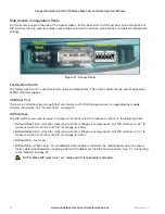
Dual Band Operation
The 915U-2 radio band is split into two sub-bands, 902–914 MHz (low) and 915–928 MHz (high). The radio
sub-band can be changed by selecting the hopset band on the Radio webpage of the Web-based configuration
utility (see “Radio Settings” on page 69).
In countries that utilize the full 902–928 MHz bandwidth (such as the United States and Canada) the 915U-2 uses
both sub-bands, which makes it possible to force the frequency hopping to the other band (high or low) to avoid
radio interference and to separate systems.
In other countries, such as Australia and New Zealand, this option is
unavailable because of the single band.
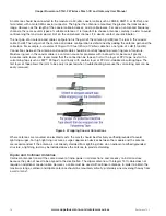
Radio Path Reliability
Radio paths over short distances can operate reliably with a large amount of path obstruction. As the path distance
increases, the amount of obstruction that can be tolerated decreases. At the maximum reliable distance, line-of-
sight is required for reliable operation. The curvature of the earth becomes more of an obstacle if the path is greater
than several kilometers (or miles), and allowance needs to be made for this. For example, the earth’s curvature over
five miles (8 km) is approx 10 feet (3m), requiring antennas to be elevated at least 13 feet (4m) to achieve line-of-
sight even if the path is flat.
A radio path may act reliably in good weather, but poorly in bad weather. This is called a marginal radio path. If the
radio path is more than 20% of the maximum reliable distance, we recommend that you test the radio path before
installation (see Chapter 6 for maximum distances). Each 915U-2 module has a radio path testing feature.
See “5.2 Mesh Connectivity” for more information.
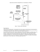
There are several ways to improve a marginal path:
• Relocate the antenna to a better position. If there is an obvious obstruction causing the problem, locating the
antenna to the side or higher will improve the path. If the radio path spans a long distance, increasing the
height of the antenna will improve the path.
• Use an antenna with a higher gain. Before doing this, make sure that the radiated power from the new antenna
remains within the regulations of your country. If you have a long coaxial cable, you can use a higher gain
antenna to cancel the losses in the coaxial cable.
• If it is not practical to improve a marginal path, you can use another module as a repeater. A repeater does
not need to be located between the two modules, although often it is. If possible, use an existing module in
the system that has a good radio path to both modules. The repeater module can be to the side of the two


