


12
www.cooperbussmann.com/wirelessresources
Cooper Bussmann 915U-2 Wireless Mesh I/O and Gateway User Manual
Rev Version 1.2.2
The power supply should be CSA Certified Class 2, approved for normal operation. If the device is being used in a
Class I Div 2 explosive area, the supply must have Class I Div 2 approval.
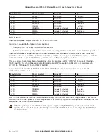
When powering the module, the power source must be able to provide sufficient current to power all module
operations, including quiescent current, peak transmit current, and digital and analog I/O, including loop supply and
battery charging (if applicable). To calculate the power supply current limit, use the following criteria.
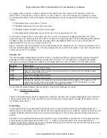
Current
@ 13.8V
@ 24V
Quiescent current of the module
200 mA
115 mA
Module maximum I/O (4xAI, 2xAO, 8xDO)
500 mA
290 mA
Peak transmit current
500 mA
290 mA
External expansion I/O
1000 mA
575 mA
Battery charging
N/A
575 mA
The following table shows t24V supply current limits with different module options enabled. Transmit current
is not added because it is not a constant.
Expansion I/O
No Expansion I/O
No battery fitted (no charging)
1270 mA
695 mA
Battery fitted
1555 mA
980 mA
The following table shows t13.8V supply current limits with different module options enabled. Transmit
current is not added because it is not a constant.
Expansion I/O
No Expansion I/O
Current limit
2200 mA
1200 mA
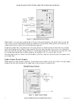
For example, if a module is powered by a 24 Vdc supply and there is no backup battery connected and it has
expansion I/O fitted, the minimum current needed is 1.3A @ 24V (32W). This is allowing for 290 mA peak transmit
current and up to 1A for the expansion I/O.
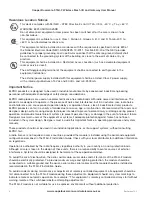
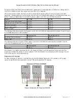
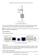
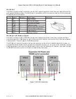
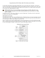
Expansion I/O Supply
To allow increased I/O capacity, a second four-way terminal labeled “Expansion I/O” provides a +12V supply
(up to 1A) and RS-485 communications for any 115S serial expansion I/O modules.
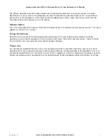
Figure 4 Expansion I/O Power and RS
-
485


