


ALSPA PROFIBUS Field Bus Coupler Appendix A.Configuration Example
(09/06)
Technical Manual
Page A5
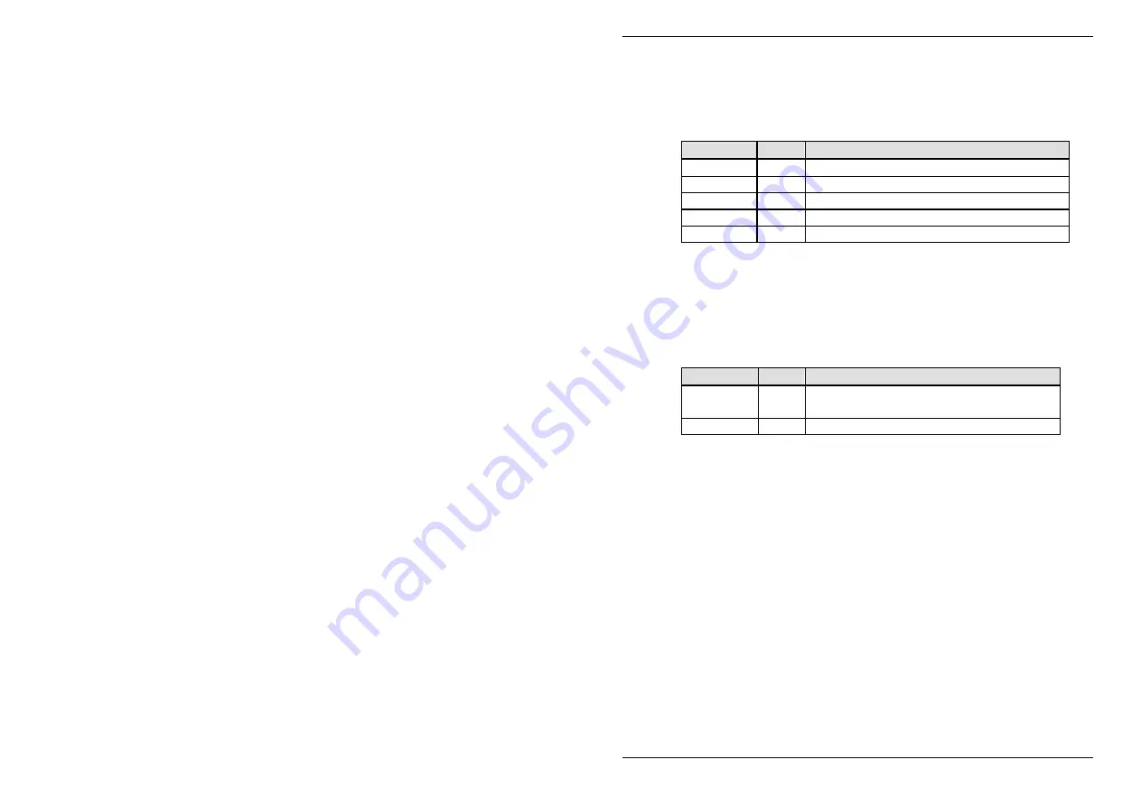
Table A-5 Speed reference set-up
Parameter Value Meaning
P5.01
21
Speed reference source 1 - use pointer 1
P5.02
0
Speed reference source 2 - not required
P5.03
0
Speed reference source 3 - not required
P5.04
0
Speed reference source 4 - not required
P5.05
0
Speed backup source – not required
Having configured the speed reference source to be menu 42
pointer 1, the final stage is to configure pointer 1 to use PZD1, set
up previously. Pointer 1 is configured in P42.00 and P42.01 as
shown in Table A-6 below.
Table A-6 Speed reference pointer 1 set-up
Parameter Value Meaning
P42.00
75.12 Pointer 1 source – P75.12 Fieldbus
reference 1
P42.01
100.00 Pointer 1 scale - 100.00%
The data transferred in the Fieldbus Reference 1 word (from PPO
PZD2) will now be used as the speed reference. Note that menu 42
allows the use of a scaling function to scale the incoming data
before it is written to the relevant reference.
This scale will also
apply to the fallback value if it used.
A.7 Control
Bits
Control bits are bits in the drive that cannot be written to directly, but
may be accessed indirectly in a similar manner to a reference.
Control bits perform such tasks as starting and stopping the drive.
This example requires access to 2 control bits, the start flag and the
stop flag. The first stage to setting up a control bit is to produce a
Fieldbus control word, which is similar to a Fieldbus reference.
Fieldbus control words are held in P75.08 and P75.10. Control word
1 (from PPO PZD1) is used in this example and control word 2
(from PZD6) may also be used. Here we will use control word 1
only, the set-up being shown in Table A-7. The start and stop bits
are transferred using control word 1.


