3. Installation
ALSPA PROFIBUS Field Bus Coupler
Page 3-4
Technical Manual
(09/06)
3.3.2 Switch
Settings
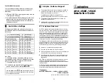
The MVS3007-4001 PROFIBUS board has two Dual-in-Line
switches, S2 and S3, which must be configured as per Tables 3-1
and 3-2.
The switches are located as shown inside the front cover.
Table 3-1 Switch S2 meanings
S2.1 S2.2 S2.3 S2.4 Dual Port RAM Address Units
On
On
Off
Off
F000 – F3FF (Hex)
MV3000e *
Table 3-2 Switch S3 meanings
Switch (S)
Jumper (X)
State
Meaning
On Not
used
S3-1
Off
PROFIBUS DP mode
*
On MV3000e
mode
*
S3-2
Off
On
Not used, must be Off
S3-3
Off
Not used, must be Off
*
On
Use PPO type 2 (10 words long)
S3-4
Off
Use PPO type 4 (6 words long)
*
On
Zero references on loss of Master
S3-5
Off
Freeze references on loss of Master
*
On Not
used.
S3-6 to
S3-8
Off Not
used.
*
1-2
Watchdog monitors drive activity
*
X23
2-3
Watchdog monitors PROFIBUS
module activity
*
Default settings/connections
3.4
MVS3007-4002 PROFIBUS Board Configuration
The switch settings and link connections that may be configured is
shown in Table 3-3. The default settings and connections are
recommended for MV3000e applications and are indicated by
asterisks
*
.


